The mass airflow sensor measures the amount of air entering the combustion chamber. It is usually located between the air filter and the throttle body. The MAF sensor signal is used by the engine control module to calculate the amount of fuel needed for ignition. In winter, the air is denser hence more fuel is injected into the ignition chamber. If the engine gets warmer the gasoline consumption will be less.
A mass air flow sensor comes with different numbers of wires. Knowing the wiring schematic of the mass air flow sensor is important for testing the sensor or doing other work. This information is important to know when diagnosing or replacing an oxygen sensor. With this knowledge, you will be able to save time and money.
In this powerful article, you will quickly learn the 3, 4, and 5-wire-MAF sensor wiring schematic.
Related Post • Oxygen Sensor: 1, 2, 3, 4 Wire O2 Sensor Wiring Diagram
Revealing How Your Car Reads Airflow
The Mass Airflow Sensors work by measuring the mass of an engine’s intake air system. The MAF sensor is typically located in the air intake tube or air filter box, and it consists of a hot connector or hot film element that is cooled by the incoming air. As the air passes over the hot element, the temperature drops, and this change is used to determine the mass of the air flowing through the sensor.
It then processes that information and sends a cue to the vehicle’s Electronic Control Unit. This cue indicates the amount of air reaching the consumption manifold so that the engine control unit can adjust gasoline delivery accordingly in order to maintain optimum ignition efficiency.
Related Post • What Is Mass Air Flow (MAF) Sensor, How it Works, & Functions
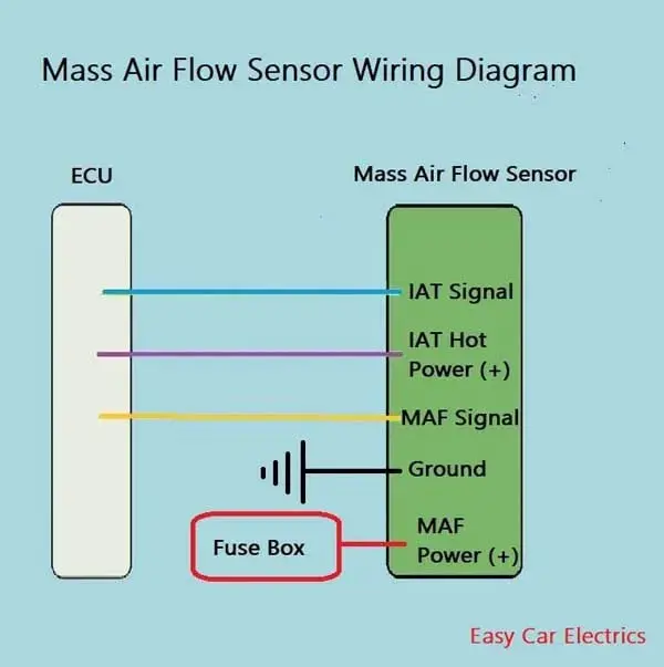
Mass Air Flow Sensor Wiring Diagram
The mass air flow wiring diagram is different according to the year, make, and model. The manufacturer designs the cabling schematic of the mass air flow sensor according to the need and demand.
In this powerful guide, we will be more general than specific. I mean, I am giving you a general idea of how the air mass sensor connections are designed.
For your specific make and model, you should check your car owner’s manual. The color of connectors will vary and are color-coded depending on the brand of the sensor.
3 Wire Mass Air Flow Sensor Wiring Diagram
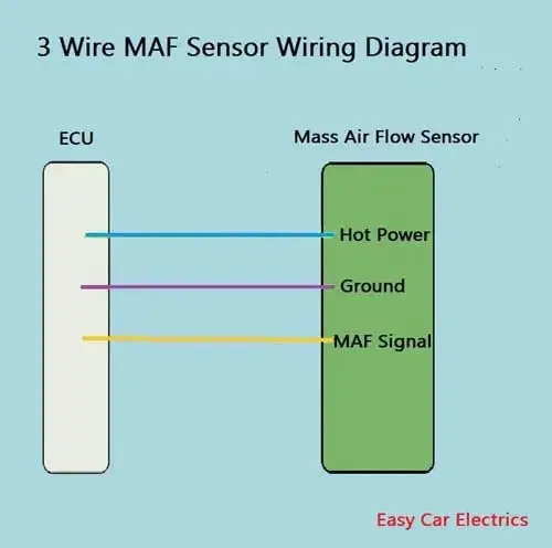
A three-wire MAF sensor consists of three wires, power, ground, and signal, which are listed below.
- Hot Power Wire (Reference voltage comes from the electronic control unit)
- Ground Wire
- Signal Wire (Gives Signals to the electronic control unit)
The hot wire is a feed power source that is taken from the car computer (electronic control unit). This is a reference voltage, which means the car’s electronic control unit Powers the MAF sensor through this wire.
The ground wire is also taken from the electronic control unit. This ground wire gives earth to the MAF sensor. A third wire is a cue (signal) wire means the transmission of the signal to the car ECU is done through this wire.
4 Pin Mass Air Flow Sensor Wiring Diagram
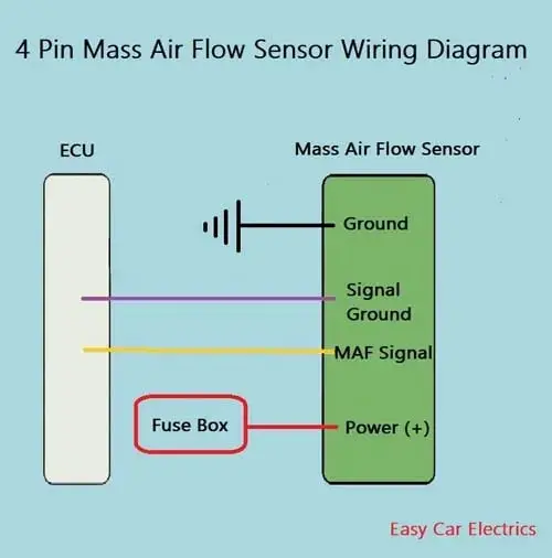
A four-wire MAF has four wires.
- 12 Volt Feed Positive Power
- MAF Cord Ground
- MAF Signal ground
- MAF Signal
A 4-wire mass air mass sensor has a 12-volt positive battery voltage, which is connected to the fuse box’s fuse and relay in the connector. The MAF cue/signal cord goes to the car’s electronic control unit. The cue/signal wire means the MAF sensor sends the Output Voltage to the ECU.
A four-wire Mass-Airflow sensor has two separate grounds. One ground is for the hot feed wire. This cord is earthed somewhere in the chassis. And the second one is for the MAF signal circuit. The MAF signal/cue circuit is given a separate ground, which is sent to the ECU.
The MAF sensor’s signal/cue circuit is placed in the MAF sensor, which calculates how much current flows to the sensor and converts that current to the voltage, and sends it to the car’s electronic control unit through the MAF signal/cue wire. This signal’s circuit is given a separate ground.
5 Wire Mass Air Flow Sensor Wiring Diagram
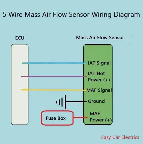
A five-wire MAF sensor consists of five wires.
- MAF Power
- MAF Ground
- MAF Signal
- Air Temperature Signal
- Air Temperature Reference Volt
A MAF sensor power connector gives a positive current to the MAF sensor. Usually, this hot power wire is taken from the fuse box’s fuse and relay. The ground wire gives earth to the MAF sensor and is usually taken from PCM, or sometimes, it is earthed somewhere in the chassis.
The MAF’s signal wire gives the cue to the electronic control unit. in the latest model cars, there is an air intake temperature (IAT) sensor integrated into the MAF sensor, which has two additional wires, a power, and a cue connector.
A power cord comes from the electronic control unit, which is usually a 5-volt reference voltage. And a cue connector goes to the electronic control unit back, informing the electronic control unit about the state of temperature of the ambient air.
This is an Info
A reference volt is a constant voltage given by the ECU to the electrical auto parts which does not change its value due to variations in temperature, loading on the device, or passage of time.
The Benefits of Having a Working MAF Sensor
1. Improved Engine Performance: The Mass Air Flow (MAF) Sensor allows for a correct air/fuel ratio within the engine’s ignition chamber, resulting in improved engine performance.
2. Fuel Efficiency: The Mass Air Flow (MAF) Sensor monitors air levels and sends this data to your car’s electronic control unit. This helps improve gasoline efficiency as the ECU adjusts the required fuel injection accordingly.
3. Hot Wire MAF Sensor Benefits: The Hot Wire (MAF Sensor) is less sensitive to location and orientation and it senses faster changes in air flow rate.
4. Humidity Control: The MAF Sensor has a platinum cord passing through the consumption path of the engine and sends information to the ECU. This helps control humidity, as the ECU adjusts fuel injection to account for humid air being less dense than dry air.
5. Accurate Measurements: The air mass sensor measures the mass flow rate of air entering a fuel-injected internal combustion engine, allowing for accurate gasoline calculations and delivery to the engine.
Related Post • How To Trick A Mass Air Flow Sensor – A Brilliant Guide
Conclusion
To sum up, understanding the (MAF )wiring schematic is crucial for troubleshooting issues related to modern engines. By knowing the connections and troubleshooting tips, you can easily identify and fix any problems. Having a good knowledge of the air mass sensor connections schematic can help keep your engine running efficiently.
FAQs
There is a possibility that the mass air flow sensor could be causing your car to stall. The (MAF) sensor measures the amount of air that is entering the engine. If there is not enough air, then the motor will not run properly it can stall and need to replace.
The number of terminals on a MAF sensor varies depending on the vehicle model. Most air mass sensors have between 4, 5, and 6 pins. Some mass-airflow meters may have more depending on the model. The exact number of terminals may vary depending on the make and model of the vehicle.
A faulty thermal sensor can cause the engine’s computer to receive incorrect temperature readings, leading to a rich or lean gasoline mixture. This can result in rough idling, decreased gasoline efficiency, and an illuminated check motor light.
To diagnose a check light of the engine on a Toyota, a diagnostic scan tool should be connected to the vehicle’s onboard diagnostic port. This tool can retrieve fault codes and live data from the vehicle’s computer. Additionally, the air inlet pipe, air cleaner, and thermal sensor should be checked, and the output voltage of the sensor’s harness should be tested.
Related • How To Test Mass Air Flow Sensor With & Without Multimeter: Expert’s Quick Guide
• How To Test Mass Air Flow Sensor With & Without Multimeter: Expert’s Quick Guide
Sign Up


Great
Kimntege, Thank You