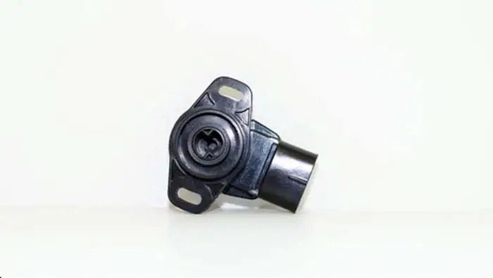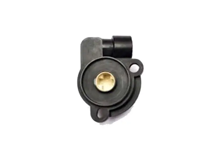
The throttle position sensor (TPS) is a device on the engine that detects the position of the throttle plate. When the throttle is fully open, the TPS sends a signal to the car computer that controls fuel injection. It also sends a signal to the ECU when the throttle is closed, so it can adjust timing and fuel delivery accordingly.
The throttle sensor wiring diagram is a schematic diagram that illustrates the electrical connections between various components within an engine or vehicle. This article will teach you the Wiring Diagram of the Throttle Sensor and electronic throttle body.
The wiring of the throttle sensor may change according to the year, make, and model. The manufacturer designs the wiring of the throttle sensor based on your requirement and need. At the end of this extremely revealing guide, we will be more general than specific. That’s it! I’m giving you a general idea about how the wiring of the TPS sensor is designed.
For your own make and model, you’ll need to check your car owner’s manual. The colors of the wires will differ and are colored according to the brand of the sensor.
Related Post: What Is Throttle Position Sensor
Throttle Position Sensor Wiring Diagram
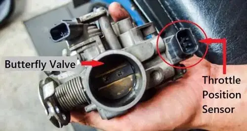
A throttle position sensor is a sensor used to monitor the position of the throttle plate in an internal combustion engine. The sensor is usually a variable resistor that produces an output voltage proportional to the throttle plate’s position. The voltage is typically used by the engine management system to control fuel injection, ignition timing, and other engine parameters.
It is usually a potentiometer, which creates a voltage based on the position of the throttle. This voltage is sent to the ECU, which uses it to make its calculations.
Rotary potentiometers are used in a wide range of applications, from volume controls on stereo equipment to the sensors that determine the air-fuel mixture in an engine. In each case, the potentiometer’s resistance varies as the wiper moves along the resistor track.
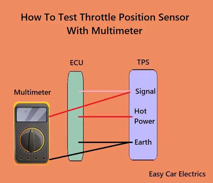
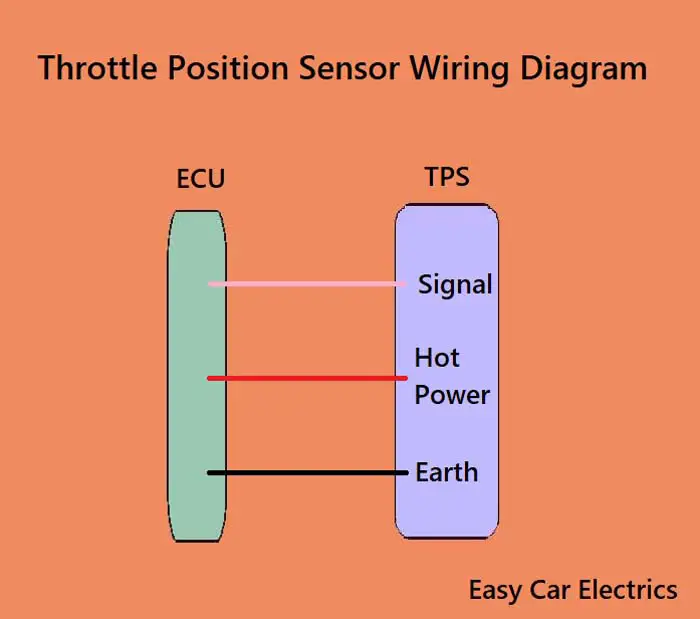
A potentiometer consists of three wires, earth, hot power, and a signal wire (wiper). The potentiometer is usually connected as part of a voltage divider circuit, with one end of the divider connected to the earth (ground) and the other end connected to some higher voltage. The signal wire is connected to the car computer. As the wiper moves along the resistor track, it varies the amount of voltage applied to the component.
The sensor reports this information to the engine control unit (ECU) so that it can regulate the air/fuel mixture and ignition timing accordingly.
3 Wire Throttle Position Sensor Wiring Diagram
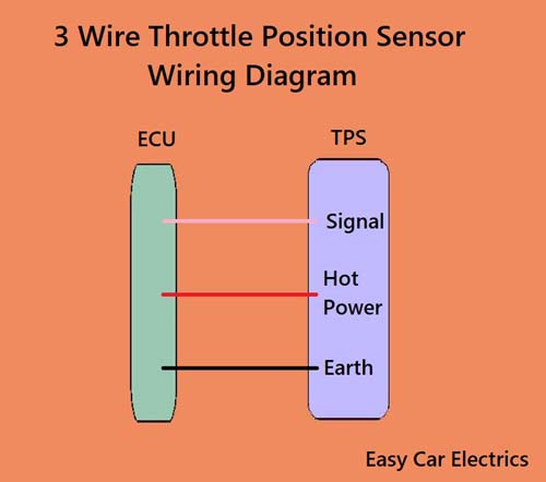
A three-pin throttle valve sensor has three wires:
- Hot Power Wire (Reference voltage comes from the ECU)
- Ground Wire
- Signal Wire (Gives Signals to the ECU)
All the wires are connected to the electronic control unit. The hot wire is a feed source that is taken from the automotive electronic control unit. This reference potential means that the auto ECU Provides 5-volt power to the throttle sensor through this wire. The ground wire is additionally taken from the ECU. This wire offers ground to the sensor.
A third wire is a signal wire which sends the information (signal) from the sensor to the engine control unit through this wire. This wire can generate a 0 to 5-volt signal. The sensor’s signal output wire should, ideally, be close to 0V when the throttle is closed and close to 5V when the throttle is wide open. The ECU monitors the signal wire and uses it to calculate the engine’s throttle position. These kinds of sensors are used in cable-operated throttle bodies.
4 Pin Throttle Position Sensor Wiring Diagram
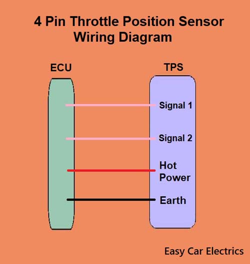
A throttle valve sensor is a type of sensor used in automotive applications to monitor the position of the throttle. A four-wire throttle valve sensor has four wires, two are the signal wires, and two are earth and hot.
- Signal Wire (Sensor 1)
- Signal Wire (Sensor 2)
- Hot Power Wire (Reference voltage comes from the ECU)
- Ground Wire
A four-pin throttle valve sensor has two potentiometers inside which have common earth and hot wires. The two signal wires are responsible for transmitting the throttle position data to the ECU, while the other two wires are used for grounding and power. The electronic control unit Supplies 5 volts of power (reference voltage) to the throttle sensor via a “hot power” wire. All the wires are connected to the car computer.
A four-wire throttle valve sensor contains two potentiometers, so it uses two signal wires to read the output of each potentiometer. This allows the sensor to accurately track the position of the throttle plate. By measuring the voltage at these two points, the sensor can determine how far open or closed the throttle is.
5 Pin Throttle Position Sensor Wiring Diagram
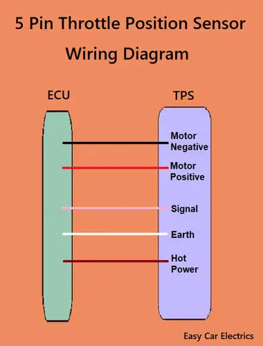
The sensor measures the angle of the throttle plate in relation to the engine and sends this information to the electronic control unit, which then adjusts things like air/fuel mixture and ignition timing accordingly.
A five-pin throttle valve sensor has one motor and one sensor. It has five wires in total, two for the motor, one signal, one earth, and one hot power wire. All the wires are connected directly to the electronic control unit.
- Motor Positive
- Motor Negative
- Signal Wire
- Hot Power Wire (5 Volt Reference voltage comes from the ECU)
- Ground Wire
The 5-pin throttle sensor’s two wires (positive and negative wires) are connected to the electronic control unit. This allows the module to control the throttle’s motor.
Another wire is the signal wire, which helps the throttle sensor supply input to the vehicle control system via this wire.
The hot wire is a power source that is taken from the electronic control unit.
This hot wire provides a 5-volt reference voltage to the throttle sensor, allowing ECU power through the wire. The last wire is the ground/earth wire that supplies earth to this throttle sensor.
6 Pin Throttle Position Sensor Wiring Diagram
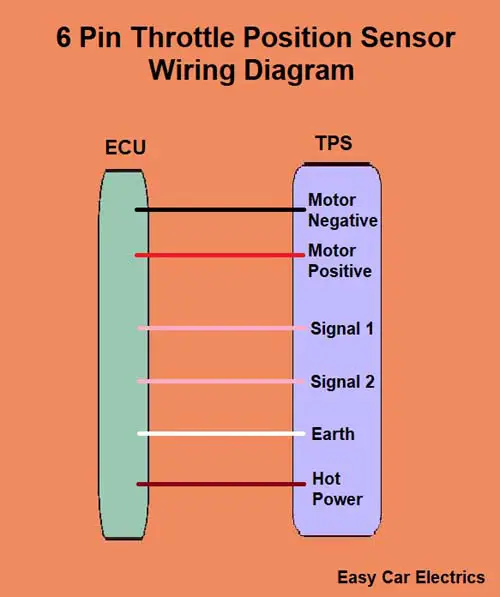
There are two types of throttle having 6-pin wiring. One is the drive-by-wire (electronic) throttle and the second is the cable-operated throttle intake body. Below is the drive-by-wire six-pin (electronic) throttle intake body diagram.
- Motor Positive
- Motor Negative
- Signal Wire (Sensor 1)
- Signal Wire (Sensor 2)
- Hot Power Wire (5 Volt Reference voltage comes from the ECU)
- Ground Wire
A six-pin electronic throttle intake body contains one motor and two potentiometers (sensors). It has six wires in total, two for the motor, two are signals, and two are earth/hot wires. These six-pin sensors have common ground and hot wires.
The hot wire is a feed power that is taken from the electronic control unit for both sensors. This hot wire provides a 5-volt reference voltage to the throttle sensor, enabling the ECU to power the throttle sensor through this wire.
The earth wire of both sensors is also taken from the ECU. This wire provides earth to the sensor. A third wire is the signal wire, which means the throttle sensor provides input to the car ECU through this wire.
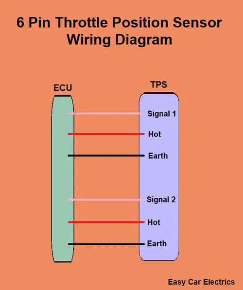
Here is the connector diagram of the cable-operated throttle intake body.
- Signal Wire (Sensor 1)
- Hot Power Wire (5 Volt Reference voltage comes from the ECU)
- Earth Wire
- Signal Wire (Sensor 2)
- Hot Power Wire (5 Volt Reference voltage comes from the ECU)
- Earth Wire
A cable-operated six-pin throttle sensor has two potentiometers (sensors). It has six wires in total, two for signals, two are earth and two are hot wires. These six-pin sensors have two separate ground, hot and signal wires. Every potentiometer (sensor) has its own separate signal, ground, and hot wires. All the wires are connected to the electronic control unit.
The 6-pin TPS sensor has two sensors for redundancy means if one sensor fails the other will still work. This is an important feature for ensuring that the throttle sensor continues to function properly even if one of the sensors fails so that you can get to the workshop. This is like having two eyes to see with – if one eye is damaged, the other one can still see.
8 Pin Throttle Position Sensor Wiring Diagram
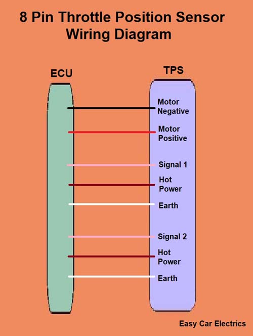
An 8-pin throttle sensor has a total of eight wires, the inside of which are two for the motor, two are signals, two are earth, and two are hot wires. These eight-pin sensors have two separate ground, hot, and signal wires. Each potentiometer (sensor) has its individual signal, ground, and hot wires.
- Motor Positive
- Motor Negative
- Signal Wire (Sensor 1)
- Hot Power Wire (Reference voltage comes from the ECU)
- Ground Wire
- Signal Wire (Sensor 2)
- Hot Power Wire (Reference voltage comes from the ECU)
- Ground Wire
An eight-pin throttle sensor contains one motor and two potentiometers. The 8-pin throttle sensor has two sensors for redundancy. If one sensor fails, the other will continue to function to keep the system functioning. This is done for redundancy, or as a backup in case something goes wrong. For example, if you have two eyes, and one is injured, the other eye can still see. This is because you have redundancy.
The 8-pin throttle sensor has two wires (positive and negative wires) for the motor that is connected to the electronic control unit. This allows the electronic control unit to control the throttle’s motor.
The feed power is taken from the electronic control unit for both sensors, which is the hot wire, which supplies a 5-volt reference voltage to the throttle sensor. This hot wire enables the ECU to power this sensor through the wire.
The ground wire of both sensors is also pulled from the ECU. This wire provides earth to the TPS sensor. A third wire is the signal wire, so the throttle sensor gives input to the car ECU through this wire.
Electronic Throttle Body Wiring Diagram
The electronic throttle intake body wiring diagram comes in two different wiring numbers. Some electronic throttle intake body has six wires while other have eight wires.
A Six wire electronic throttle intake body has two wires for the motor, two are signals and two are earth/hot. It has common earth and hot wires. It has the same connector diagram, we covered in the six-pin connector diagram. I am again posting the diagram of the six-pin electronic throttle intake body here.
- Motor Positive
- Motor Negative
- Signal Wire (Sensor 1)
- Signal Wire (Sensor 2)
- Hot Power Wire (Reference voltage comes from the ECU)
- Ground Wire
The eight-wire electronic throttle intake body connector diagram is the same covered in the eight-pin throttle sensor connector diagram. It has two wires for the motor – two are signal, two are earth and two are hot wires. I am posting again the diagram of the eight-pin connector diagram.
- Motor Positive
- Motor Negative
- Signal Wire (Sensor 1)
- Hot Power Wire (Reference voltage comes from the ECU)
- Ground Wire
- Signal Wire (Sensor 2)
- Hot Power Wire (Reference voltage comes from the ECU)
- Ground Wire
An electronic throttle intake body has one motor and two sensors for redundancy means if one sensor breaks the other still functions. The two sensors measure how much air is coming into the engine. If one sensor fails, the other sensor can still measure how much air is coming in, so the engine will still work. So, if one goes bad, the other can still send information to the electronic control unit. This is done as a backup in case something goes wrong with one of the sensors.
The electronically controlled throttle intake body has two wires (which are a little thick) for the motor’s positive and negative that are connected to the car’s electronic control unit. This allows the electronic control unit to monitor and control the throttle’s position.
When the driver presses the accelerator pedal, a signal is sent to the car’s electronic control unit, telling it how much power is needed. The electronic control unit then sends power to the electronic throttle body through these positive and negative wires of the motor.
The electronic throttle sends a signal to the electronic control unit which then calculates how much fuel to inject into the engine in order to maintain the desired air-fuel ratio and timing accordingly. The electronic control unit also uses input from other sensors, such as the mass airflow sensor and the throttle sensor, to make its calculations.
The signal wires send a signal to the electronic control module to tell it how far the throttle plate (butterfly valve) is open. These two signal wires carry the voltage that is used to determine the position of the throttle plate, while the earth and hot wire provide power and ground to the sensor.
Related Post: How To Calibrate (Reset) Throttle Position Sensor (7 Steps)
FAQs
A TPS sensor has between 3 to 8 wires. The number of wires depends on the specific sensor and the make and model of the vehicle. All of the sensors have basic three wires. The first wire is the power wire, the second wire is the earth wire, and the third wire is the signal wire. Some TPS sensors have dual sensors in one unit, and some have an electric motor that increases the number of wires. Its harness is an electrical cable that acts as a conduit for electrical signals between the sensor and other components that are located within the vehicle, such as the engine management systems.
There is no fuse for the throttle sensor; however, there is a fuse for the ECM. The ECM controls the throttle sensor, so if the ECM fuse is blown, the sensor will not work.
The three basic wires on a TPS sensor are the power wire, the earth wire, and the signal wire. The power wire provides power to the sensor, the earth wire provides a path for the current to flow, and the signal wire sends a signal to the ECU.
The most common symptoms of a failed throttle sensor are poor acceleration, rough idle, and a check engine light on your dashboard. Other signs include lacking power when accelerating, slow or rough idle, stalling, difficulty shifting gears, and the check engine light turning on. If you notice any of these symptoms, it is important to have your throttle sensor inspected by a professional mechanic.
Yes, disconnecting the battery will reset the throttle sensor. However, this is only a temporary solution and the sensor may need to be recalibrated after reconnecting the battery. To do this, you can disconnect the battery for up to five minutes. Additionally, you may need to replace the throttle sensor if it does not reset. The average cost for throttle sensor replacement is between $157 and $201.
A faulty throttle sensor can cause OBD-2 codes. In order to test a 6 wire throttle sensor, one must first determine the electrical characteristics of the individual wires (attached to the throttle). This can be done by measuring the voltage and resistance of each terminal with a digital multimeter. Once the electrical characteristics are known, it is necessary to connect the wires in a specific configuration based on the manufacturer’s instructions.
Sign Up