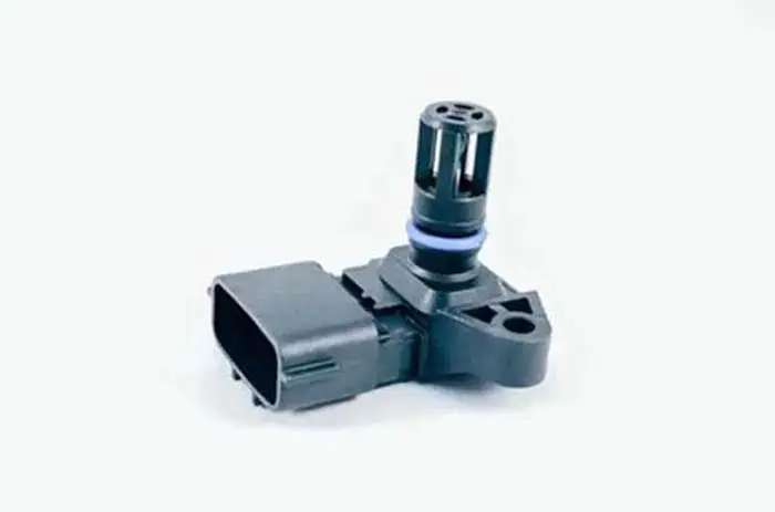
A MAP sensor or manifold absolute pressure sensor is a device that measures the pressure inside the intake manifold of an internal combustion engine. The pressure measurement is used to calculate the amount of air flow into the engine.
Sure, this information is used by the engine control unit (ECU) to adjust the fuel injector timing and air/fuel mixture. A failing sensor won’t provide the right data to the ECM and need to be replaced.
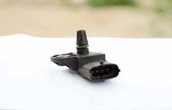
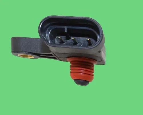
Map sensors are typically located on the side of the intake manifold near the throttle body. The sensor works by the changes induced by the intake air pressure applied on the silicon chip. This sensor plays an important role in the performance of an engine.
The number 1 use of this sensor electrical diagram is to help identify and understand the connection between the map sensor and the engine control unit. Without this part, the car will not respond like it normally does and the vehicle will unable to function properly. The sensor comes in different electrical diagrams and colors depending on the car. In this powerful guide, we will discuss the 3 and 4-pin MAP sensor wiring diagram.
Related Post: What Is MAP Sensor In A Car, How Does It Work, & Functions
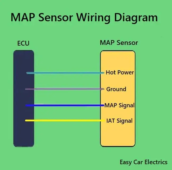
MAP Sensor Wiring Diagram
The Manifold Air Pressure Sensor or MAP Sensor wiring diagram can be different according to the year, make, and model.
In this powerful guide, we will be more general than specific. Here, I will give you a general idea of how the MAP sensor wiring is designed. For your specific make and model, check the car owner’s manual. The color of wires will vary and are color-coded depending upon the brand of the sensor.
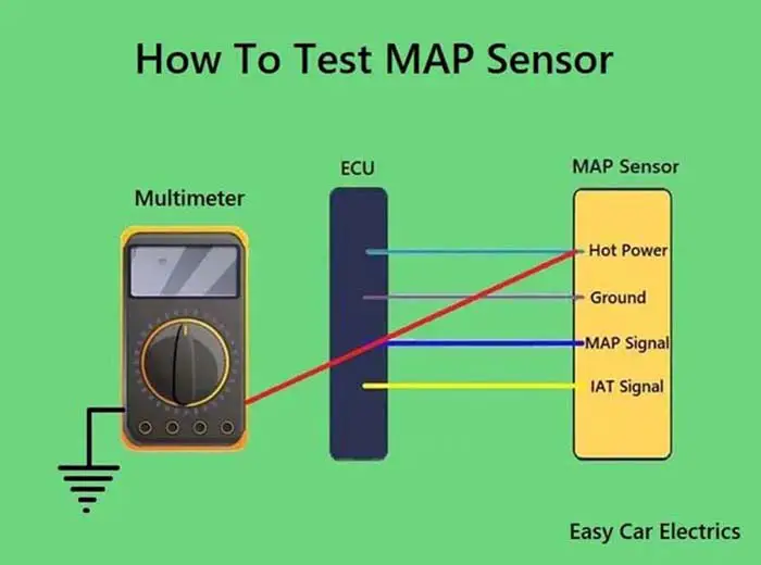
Related Post: How To Test MAP Sensor
3 Pin MAP Sensor Wiring Diagram
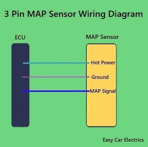
A three-wire MAP sensor has three wires in one connector, power, ground, and signal, which are listed below.
- Hot Power Wire (5 Volt Reference Voltage comes from the ECU)
- Ground Wire
- Signal Wire (Gives Signals to the ECU)
The hot wire is a feed power source that is connected to the car computer (ECU). This is a reference voltage, which means the car ECU Powers this pressure sensor through this wire.
The ground/earth wire is also taken from the ECU. This earth wire gives earth to this pressure sensor. A third wire is a signal wire means the MAP sensor delivers the data (signal) to the car ECU through this wire.
Related Post: How To Reset Map Sensor: The Ultimate Guide
4 Pin MAP Sensor Wiring Diagram
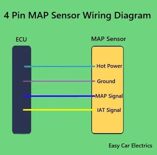
A four-wire manifold air pressure sensor has the following four wires.
- 12 Volt Feed Positive Power Wire
- Ground Wire
- MAP Signal Wire
- Intake Air Temperature (IAT) Sensor Signal Wire
A 4-wire manifold absolute pressure sensor has a 5-volt reference voltage, which is connected to the car computer (ECU). A reference voltage means the ECU provides the voltage to the sensor.
The ground/earth wire also goes to the car ECU. The MAP Signal Wire goes to the car ECU. The signal wire means the sensor sends the Output Voltage to the ECU.
A four-wire MAP sensor has an additional sensor called the intake air temperature sensor. It has only an IAT signal wire, which sends the temperature of the air inside the intake manifold to the car computer.
Related Post: What Happens If You Unplug A Map Sensor
Sign Up