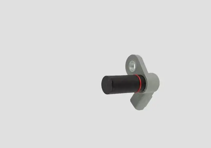
The camshaft position sensor is an electronic sensor used to locate the position of the engine’s camshaft and converts it into an electronic signal then send it to the car ECU.
It detects the location of the camshaft and its angle in order to determine the position of the engine cylinder’s piston to be operated.
The camshaft position sensor comes with a different wiring diagram. below is the ultimate guide about the camshaft position sensor wiring diagram.
In this powerful guide, you will learn two and three-wire camshaft position sensor wiring diagrams in easy-to-understand language.
Camshaft Position Sensor Wiring Diagram
The wiring diagram of the camshaft position sensor is different according to the year, make, and model. In this powerful guide, we will be more general than specific. I mean, I am giving you a general idea of how the camshaft position sensor wiring is designed.
For your specific make and model, you should check your car owner’s manual. The color of wires will also vary and are color-coded depending upon the brand of the sensor. Below are the two and three-wire camshaft position sensor wiring diagrams.
2 Wire Cam Sensor Wiring Diagram
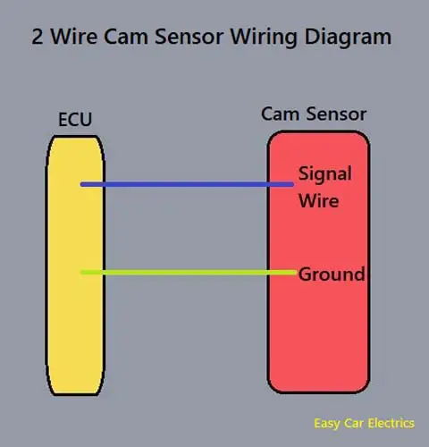
The two-wire camshaft position sensor has two wires.
- Ground
- Signal Wire
The two-wire camshaft position sensor has a ground wire, which is necessary for the current to complete an electrical circuit. The second is the signal wire through which the camshaft position sensor sends its voltage to the ECU. Both wires are connected to the car computer (ECU).
A two-wire camshaft position sensor is usually an inductive type sensor, which consists of a sensor magnet and coil. When the camshaft’s reluctor ring comes closer to the crank sensor, voltage is produced, which is sent to the computer.
An inductive type crankshaft position sensor is also known as a magnetic pick-up sensor. It has two wires, an earth, and a signal (voltage) wire.
Do you know why the inductive types crank sensor has two wires? Or why there are two wires camshaft position sensor.
It is because the cam sensor has a coil (and magnet as well), which produces its own magnetic flux. And at the end voltage in the coil is also produced, when the crankshaft’s reluctor ring comes closer to it. It does not need a positive outside voltage source wire to energize it.
It can generate a signal (output voltage produced by the cam sensor), which is then sent to the ECU without giving it a positive current. This is the reason the inductive-type camshaft position sensor has two wires. So, whenever you see a two-wire sensor, realize that it is an inductive type sensor.
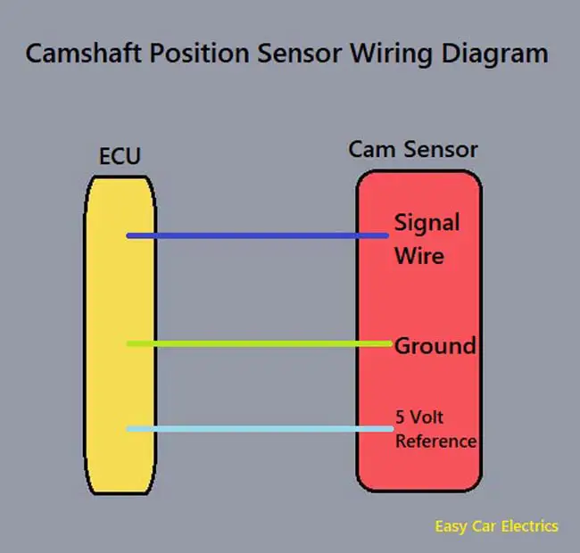
3 Wire Cam Sensor Wiring Diagram
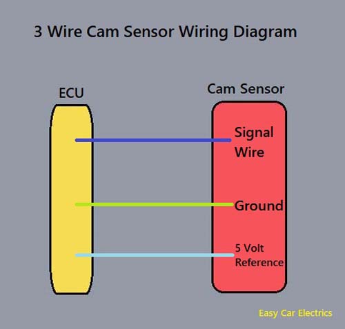
The 3 wire crank sensor has three wires mentioned below.
- Reference Voltage Wire
- Signal Wire
- Ground
All of these wires are connected to the ECU. A 3 wire cam sensor receives a hot power source called reference voltage from the ECU. The sensor’s ground is also taken from the ECU and lastly, the signal voltage wire goes from the sensor to the ECU (computer).
A three-wire sensor is usually a hall-effect type sensor. These types of sensors have a magnet and a steel-type material like germanium and a transistor.
So, when an object comes closer to the hall-effect sensor, its magnetic flux changes, and as a result, voltage is produced in the material, which is amplified by the transistor and sent to the car computer.
The hall-effect sensor must be additionally supplied by the external voltage which is needed for integrated electronics (transistors). They usually supply positive power sources mainly 5 volts but in some cases can be 12 volts.
The camshaft position sensor consists of three wires; one for voltage and the other two wires are ground and signal wire (the signal wire goes to the computer from the sensor). This voltage is very low; an amplifier circuit (transistor) is built up in the sensor to amplify the voltage.
The reference voltage is the voltage, which is given by the car computer (ECU) to the sensor, and the signal voltage is the voltage, which is given by the sensor to the car computer (ECU).
Related Post: How To Test 2 & 3 Wire Camshaft Position Sensor W/Multimeter
FAQs
When discussing a camshaft sensor, it is important to note that there are two different types – a 2-wire and a 3-wire. The number of wires will vary depending on the specific model and make of the sensor. Each type of camshaft sensor has a different number of wires, which impacts the way in which the sensor functions.
The cam sensor should have a reference voltage of either 5 or 12 volts. The 5-volt reference is the most common and is used on most vehicles. The 12-volt reference is less common and is used on some high-performance engines.
A camshaft position sensor can cause transmission problems because it senses the position of the camshaft and sends a signal to the engine control unit. If the sensor is not working properly, the engine control unit may not be able to control the engine properly, which can cause the transmission to slip or not shift properly.
Related Post: Oil On Camshaft Position Sensor: Is It A Sign Of Failure
Sign Up