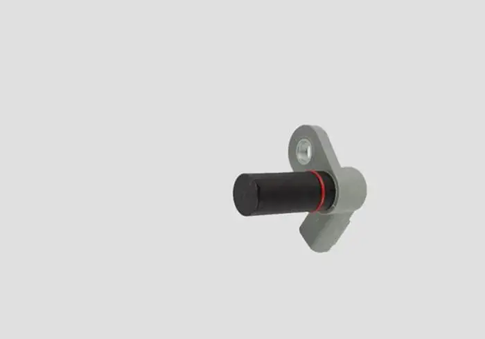
A camshaft Position Sensor is one of many electronic sensors that are incorporated into your vehicle. This sensor is by far one of the most important sensors and constitutes the fundamental operation of the vehicle along with the Crankshaft Position Sensor of the vehicle.
The function of the Camshaft Position Sensor is to calculate the rotations of the Camshaft of the engine and to determine the position of the Camshaft.
As the Camshaft Position Sensor is very important, if the Camshaft Position Sensor of the vehicle gets bad, the vehicle faces damage and it could mess your vehicle up greatly. Luckily, we have got your back, we will be explaining to you how to test the bad camshaft position sensor.
In this powerful article, you will learn how to test two and three-wire camshaft position sensors with a multimeter (With Pictures).
How To Test Camshaft Position Sensor With Multimeter
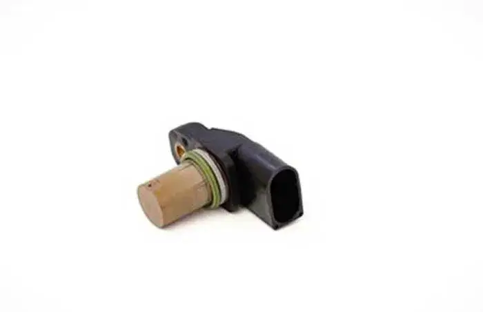
There are two types of Camshaft Position Sensors, one has two wires known as Magnetic or Inductive type Camshaft Position Sensor and the other has three wires known as Hall Effect Camshaft Position Sensor.
Below is the step-by-step testing procedure for the two and three-wire camshaft position sensor.
How to Test 2 Wire Cam Sensor With Multimeter
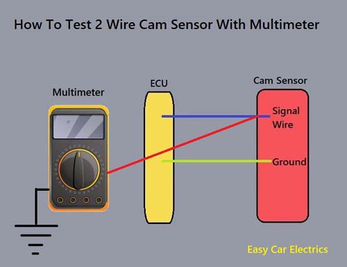
To test the two-wire or Inductive Type Camshaft Position Sensor, we need to run some tests with the help of a Digital Multimeter. Here is how to test An Inductive Camshaft Position Sensor:
- First of all, shift the gear or the transmission of the vehicle to parking or neutral in case of a manual vehicle.
- Once you have done that, you should put the vehicle on emergency brakes.
- Now, identify the ground and signal wires.
- Turn the setting of the Digital Multimeter to DC volts.
- Connect the red cable of the Digital Multimeter to the back of the signal wire at the connector and the black lead of the Digital Multimeter to the battery negative terminal to check the voltage (signal) of the two-wire camshaft position sensor.
- Crank the engine and check the voltage that the harness connector gives off. The signal received by the Digital Multimeter is close to 1.5 volts. Different vehicles give off different voltages, depending on the model of your vehicle. You can consult the repair manual of the vehicle to get the exact voltage of your vehicle.
- Now, to check the ground of the cam sensor, turn the Digital Multimeter to connectivity Mode.
- Back probe the harness connector’s ground wire to the red lead of the multimeter and the black lead of the Digital Multimeter to the battery negative terminal.
- You will hear a beep sound which indicates that the sensor’s ground is working.
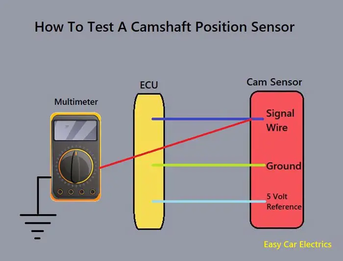
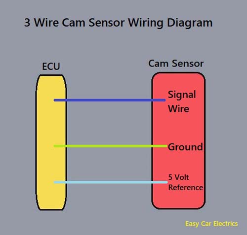
How to Test 3 Wire Cam Sensor With Multimeter
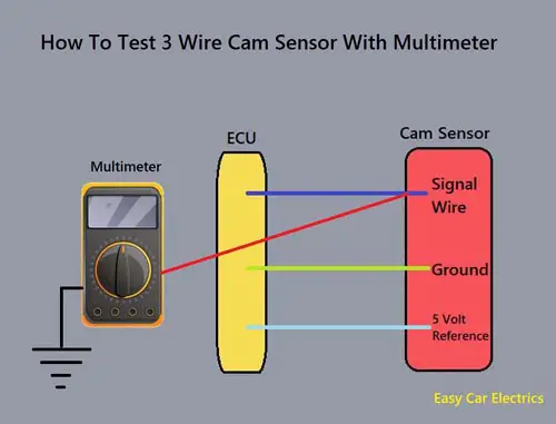
A three-wire cam sensor is of a Hall Effect type Camshaft Position Sensor, which produces a squared and digital signal. This signal represents the highest and the lowest possible points of voltage. Here is how to test three-wire cam sensors with a multimeter.
- Shift the gear or the transmission of the vehicle to parking or neutral in case of a manual vehicle.
- Once you have done that, you should put the vehicle on emergency brakes.
- Set the Digital Multimeter to the DC voltage settings.
- Now, you will have to back probe the harness connector’s power/reference wire to the red lead of the Digital Multimeter and connect the black lead of the Digital Multimeter to the negative terminal of the battery.
- Ask someone to start the engine for you, so you can note the reading on the Digital Multimeter.
- The reading on the screen of the Digital Multimeter must be 5 volts (some vehicles use 12 volts).
- Once you are done checking the power wire, turn the Digital Multimeter to the connectivity mode.
- Now, you will have to back probe the harness connector’s ground wire to the red lead of the Digital Multimeter. Connect the black lead of the Digital Multimeter to the negative terminal of the battery of the vehicle.
- You will hear a beep sound which indicates that the sensor’s ground is working.
- Now coming on to the last wire, back probe the signal wire of the Camshaft Position Sensor to the red lead of the Digital Multimeter. Connect the black lead of the Digital Multimeter to the negative terminal of the battery.
- Ask someone to start the vehicle’s engine so you can note the reading on the screen of the Digital Multimeter.
- The reading on the screen of the Digital Multimeter should be 0 to 5 volts if the Camshaft Position Sensor is working correctly, if not, you must get the Camshaft Position Sensor replaced by a mechanic.
Related Post: 2 & 3 Wire Camshaft Position Sensor Wiring Diagram With Pics
FAQs
The camshaft position sensor should have an internal resistance value of 200 to 1,000 ohms. This range is optimal for ensuring that the sensor is able to accurately detect the position of the camshaft and relay this information to the engine control unit. If the sensor has too high of a resistance value, it may not be able to properly detect the camshaft’s position. Conversely, if the sensor has too low of a resistance value, it may produce inaccurate readings.
There are a few possible causes of low voltage to the camshaft sensor. One possibility is that the sensor itself is faulty and needs to be replaced. Another possibility is that the engine is not getting enough power from the battery. This could be due to a problem with the battery itself, or with the alternator. Additionally, if there is something wrong with the wiring between the battery and the sensor. This could be due to a loose connection, or a break in the wire.
While camshaft position sensors can vary in their design, many of them are magnetic. This is because a magnetic field can be used to detect the position of the camshaft. The sensor usually consists of a magnet and a coil of wire. When the camshaft turns, the magnet moves with it. This movement changes the magnetic field, which induces a voltage in the coil of wire. This voltage can then be used to determine the position of the camshaft.
Sign Up