The crankshaft position sensor is an electronic sensor that measures the position of the crankshaft. There are two most common types of crankshaft position sensors that are used commonly in the car.
One is the inductive coil pick-up crank sensor, which produces an alternating current in the coil and the other is the Hall-effect crank sensor.
The Hall-effect crankshaft sensor generates the digital square wave signal and sends it to the ECU of the car. Most modern cars use the Hall-effect crankshaft sensors because of their more accurate readings. The inductive pick-up coil sensors have two wires whereas the Hall-effect sensors have three wires.
In this amazing powerful guide, we will discuss the 2 and 3 wires crank sensor wiring diagram.
What is a Crankshaft Position Sensor
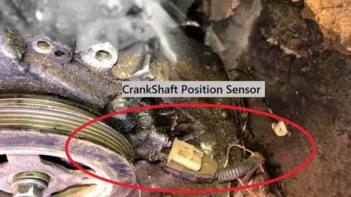
A Crankshaft Position Sensor (CKP) is an electronic device used in an internal combustion engine, both petrol and diesel, to monitor the position or rotational speed of the crankshaft. This information is used by engine management systems to control the fuel injection or the ignition system timing and other engine parameters.
The crankshaft sensor measures the rotation speed (engine RPM) and the precise position of the engine crankshaft. The fuel injection system uses the crank position sensor to make synchronization of the fuel injectors and, in addition, the crank position sensor keeps track of the engine’s speed.
Related Post: Crankshaft Position Sensor: How It Works, & Functions
Crank Sensor Wiring Diagram

The electrical diagram of the crankshaft sensor is different according to the year, make, and model. The manufacturer designs the electrical schematics of the crank position sensor according to the need and demand.
In this powerful guide, we will be more general than specific. I mean, I am giving you a general idea of how the crank position sensor wiring is designed.
For your specific make and model, you should check your car’s owner manual. The color of wires will also vary and are color-coded depending upon the brand of the sensor. Below are the two and three-wire crank position sensor electrical schematics.
2 Wire Crank Sensor Wiring Diagram
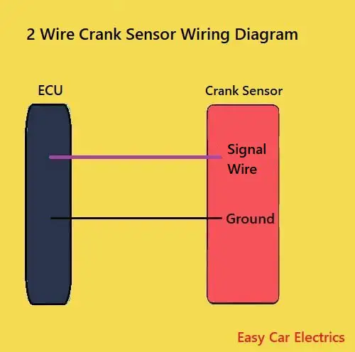
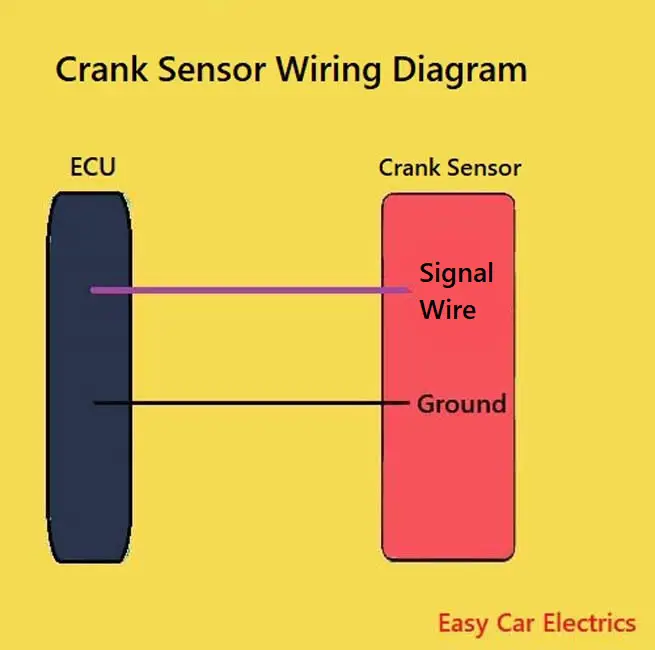
The two-wire crankshaft position sensor circuit has two wires.
- Signal Wire
- Ground
The two-wire crank position sensor has a signal cord through which the crankshaft sensor sends its voltage to the ECU. The second is the ground cord, which is necessary for the current to complete an electrical circuit. Both wires are connected to the electronic control unit.
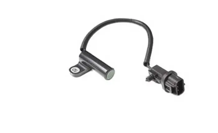
A two-wire crankshaft sensor is an inductive type sensor, which consists of a sensor magnet and coil. When the crankshaft’s reluctor ring comes closer to the crank sensor, voltage is produced, which is sent to the car computer.
The inductive-type crank position sensor is also known as a magnetic pick-up sensor has two wires, an earth, and a signal (voltage) wire.
Now the question is why the inductive types crankshaft sensor has two wires. Or why there are two wires crankshaft position sensor.
It is because it has a coil (and magnet as well), which produces its own magnetic flux and at the end voltage in the coil when the crankshaft reluctor’s ring comes closer to it. It does not need a positive outside voltage source wire to energize it.
It can generate a signal (output voltage produced by the crankshaft sensor), which is then sent to the electronic control unit without giving it a positive current. This is the reason the inductive-type crankshaft position sensor has two wires. So, whenever you see a two-wire sensor, realize that it is an inductive type sensor.
3 Wire Crank Sensor Wiring Diagram
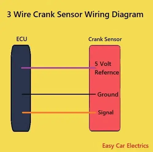
The above image contains the diagram for 3 wires. The 3 wire crankshaft sensor has three wires mentioned below.
- Reference Voltage Wire
- Signal Wire
- Ground
All of these wires are connected to the electronic control unit. A 3 wire crankshaft sensor receives a hot power source called reference voltage from the electronic control unit. The sensor’s ground is also taken from the electronic control unit and lastly, the signal voltage wire goes from the sensor to the computer.
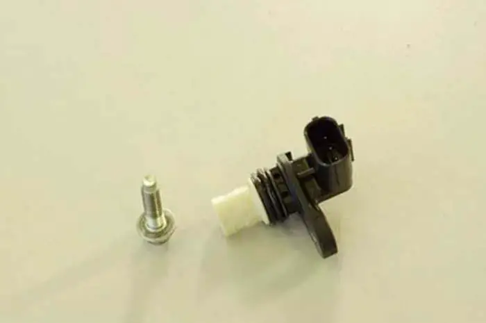
A three-wire sensor is usually a hall-effect type sensor. These types of sensors have a magnet and a steel-type material like germanium and a transistor.
So, when an object comes closer to the sensor, its magnetic flux changes, and as a result, voltage is produced in the material, which is amplified by the transistor and sent to the electronic control unit.
The hall-effect sensor must be additionally supplied by the external voltage needed for integrated electronics (transistors). They usually supply positive power sources mainly 5 volts but in some cases can be 12 volts.
It consists of three wires; one for voltage and the other two wires are ground and signal wire (the wire goes to the computer from the sensor). This voltage is very low; an amplifier circuit (transistor) is built up in the sensor to amplify the voltage.
The reference voltage is the voltage, which is given by the ECU to the sensor, and the signal voltage is the voltage, which is given by the sensor to the car computer (ECU).
Difference Between Hall Effect And Inductive Type Crank Sensor
The difference between both sensors is, the Hall Effect crankshaft sensor must be given the voltage, without giving the voltage, it would not work. Because the Hall Effect crankshaft sensor has an integrated circuit and needs an outside power source to work, which amplifies the voltage.
That’s why it has three wires, earth, voltage, and a signal wire. The coil or inductive-type crankshaft sensor needs no voltage because it produces the voltage itself when an object comes closer to it. And it has two wires earth and a signal wire. It does not need a voltage source to function.
Related Post: How To Test 3 Wire Crank Sensor With Multimeter & Testing 2 Wire Crank Sensor
FAQs
The 3 wires on the crankshaft position sensor are Reference Voltage Wire, Signal Wire, and Ground Wire. All are connected to the ECU.
The resistance of the good working crankshaft sensor is 200Ω to 2000Ω. If the resistance is zero ohms, it indicates a short circuit. When determining the amount of resistance a crankshaft sensor should have, a variety of factors must be considered. The kind of engine, the age of the engine, and the operating conditions all play a role in how much resistance the sensor should have. In general, newer engines will have sensors with less resistance than older engines. Additionally, engines that are operated in harsher conditions (e.g., high temperatures or dusty environments) will also have sensors with less resistance.
A hall-effect type sensor that has three wires will often have a magnet and a steel-type substance called germanium and a transistor. So, a 3 wire crankshaft sensor works by detecting changes in the magnetic flux of an object when it comes near the sensor. This creates an electrical voltage, which is sent to the ECU.
Crank no-start can be caused by a variety of sensors, such as the crankshaft position sensor, the throttle position sensor, the coolant sensor, and the fuel pump, etc. These sensors can either fail or have their wiring damaged, resulting in the engine either stalling or not starting at all. In some cases, the engine may crank but not start, in that case, the issue is likely not related to the battery, cables, or starter motor. Other possible causes include a bad fuel pump or a clogged fuel filter. In some cases, a lack of timing signal from the CKPS crankshaft position sensor to the ECU may also be the cause.
To test a 3 pin crankshaft sensor, you will need a multimeter set to DC voltage. First, identify the power, ground, and signal wires using your vehicle’s manual. Then, unplug the crankshaft position0 sensor and connect one multimeter lead to one of the sensor’s pins and the other multimeter lead to another pin. Finally, take readings from the signal, reference, and ground wires and compare them to the indications contained in the car manual. If the readings are not in coherence, then your crankshaft sensor is bad.
Sign Up