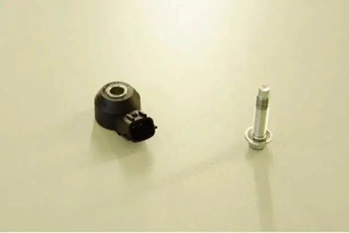
A knock sensor is a device to detect the sound of the combustion in the engine cylinder very precisely. The detected vibration and sound are then converted into signals and then send to the engine control module which processes them.
The information is then analyzed by the engine control module, which determines whether or not ignition timing should be changed. A knock sensor is usually mounted on the outside of the engine block, but it can also be found beneath the intake manifold in some situations.
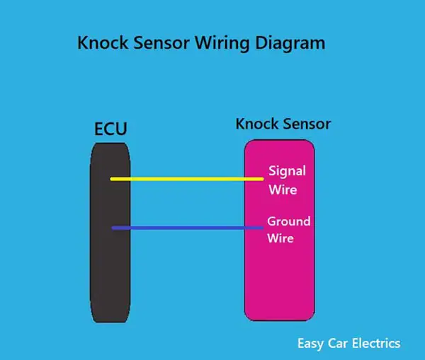
A wiring diagram is a simplified conventional photographic representation of an electric circuit. It shows the components of the circuit as simplified forms and the power and signal connections between the devices.
Figuring out a knock sensor wiring diagram is not a fun job. This article will make it easier for you. The wiring diagram below shows the typical wiring configuration for a knock sensor so that you know how to correctly connect the knock sensor to the car’s electrical system.
Knock Sensor Wiring Diagram
This guide will provide a more generalized overview of how the wiring is designed, rather than specifics on every single installation. The wiring diagram of the knock sensor is different according to the year, make, and model. But the main function and main circuit diagrams will be the same showing the information flow and current flow through the sensor and then output going to the electronic control module. If you are not sure which wiring diagram to use for your car, you can always consult the manufacturer.
For some reason, one particular wire on your car’s sensor may be color-coded differently from the rest. In order to determine which wire goes to which sensor, you’ll need to consult your owner’s manual or look it up online. Each brand of sensor will have a different color code for the wires, so make sure you’re getting the right one.
Related Post: Car Knock Sensor: What It Does, How It Works & Why It Occurs
1 Wire Knock Sensor Wiring Diagram
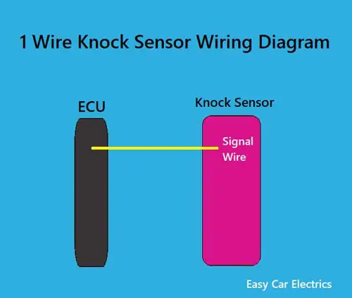
- Signal Wire
A one-wire knock sensor has one signal wire. When knocking occurs, the vibrations in the block cause a current to flow through the signal wire, which is detected by the knock sensor. This sensor is earthed (connected to the ground) via the body of the sensor, which is in contact with the engine block to complete the electrical circuit.
Note: A signal wire means a wire which carries voltage from the sensor to the car computer. Here, in the knock sensor, a signal wire carries the voltage produced by the knock sensor to the car computer when knocking occurs.
2 Wire Knock Sensor Wiring Diagram
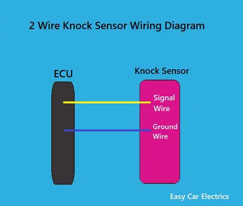
- Signal Wire
- Ground Wire
The knock sensor has two wires, one for the signal and one for the ground. When the knock sensor detects a knocking noise, it sends a signal to the ECU (engine control unit) to adjust the fuel injection and ignition timing accordingly. The sensor gets both wires from the ECU.
The two-wire knock sensor has two wires, each of which is needed to complete a circuit that passes an electrical current. The first is the ground wire, the ground wire is an essential part of a full circuit for the wire to complete a circuit. The second wire is the signal wire, through which the knock sensor sends the electric current to the ECU. Both wires are connected to the car computer (ECU).
3 Wire Knock Sensor Wiring Diagram
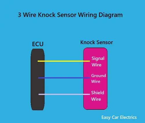
- Signal Wire
- Ground Wire
- Shield Wire
A three-wire knock sensor has three wires signal, a ground, and a shield wire. The signal wire sends a message to the ECU when a knock is heard. The ground wire ensures that electricity flows properly to the sensor. The shield wire prevents electrical interference from other devices.
The three-wire knock sensor is the same as the two-wire knock sensor. They both have a signal and a ground wire. The only difference between these two types of knock sensors is that the three-wire knock sensor has a third extra wire called shield wire which protects the knock sensor wiring from electromagnetic interference.
A Shield wire is a type of electrical wire that helps protect against electrical interference. It is typically used in conjunction with other types of wiring and is wrapped around the other wires to create a shield. This helps keep unwanted electrical signals from entering or exiting the wire, which can cause interference in the electrical system. The shield wire helps to ensure that the sensor accurately detects knocking.
The shield wire must be connected to the ground at the ECU end in order to protect the circuit from electrical noise and to ensure that the signal is not distorted. Connecting the shield wire to the ground helps to keep the signal strong and clear, while also preventing any interference from outside sources.
FAQs
There are a few different types of knock sensors, each with a different number of wires. One type has one wire, another has two wires, and the last type has three wires. The make and model of the car will determine which type of knock sensor it uses.
No. they do not. Knock sensors are piezoelectric, which means that they generate an electric potential in response to applied mechanical stress. It is designed to detect knocking or pinging sounds in an engine, and as such, they do not need to have polarity in order to function properly.
The knock sensor is an important part of the engine management system, and it is typically grounded at the ECU. This helps to ensure that the sensor is able to accurately detect engine knock and relay this information to the ECU.
Related Post: How To Check If A Knock Sensor Is Bad? Fast & Easy Way
Sign Up