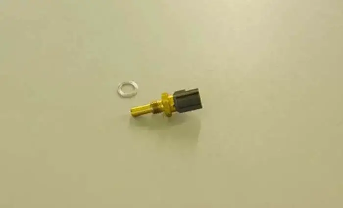
One of the most important sensors in your vehicle is the coolant temperature sensor. This sensor is responsible for telling the computer what the engine coolant temperature is. The computer uses this information to adjust the fuel mixture and ignition timing.
A coolant temperature sensor wiring diagram is essential for understanding how a car’s engine cooling system works. It can help you troubleshoot issues with the cooling system and avoid costly repairs. The ECT sensor comes in different wiring diagrams and colors depending on the car. In this powerful article, we will explain how to read the 1, 2, and 3-wire coolant temperature sensor wiring diagram.
Related Post: Where Is The Engine Coolant Temperature (ECT) Sensor Located
What is Coolant Temperature Sensor
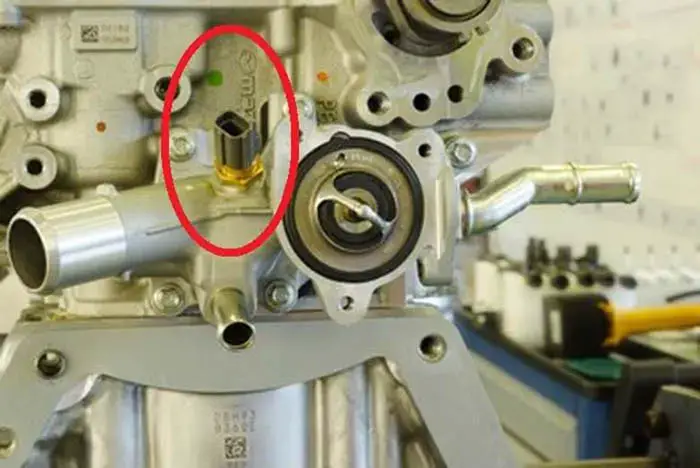
The engine coolant temperature (ECT) sensor is a resistor-based sensor, which measures the temperature of the engine’s coolant. It sends the reading to the car computer (ECU), which adjusts the amount of fuel intake into the combustion chamber. This sensor is typically mounted on the engine block and is in link to the engine coolant.
Types of Coolant Temperature Sensors
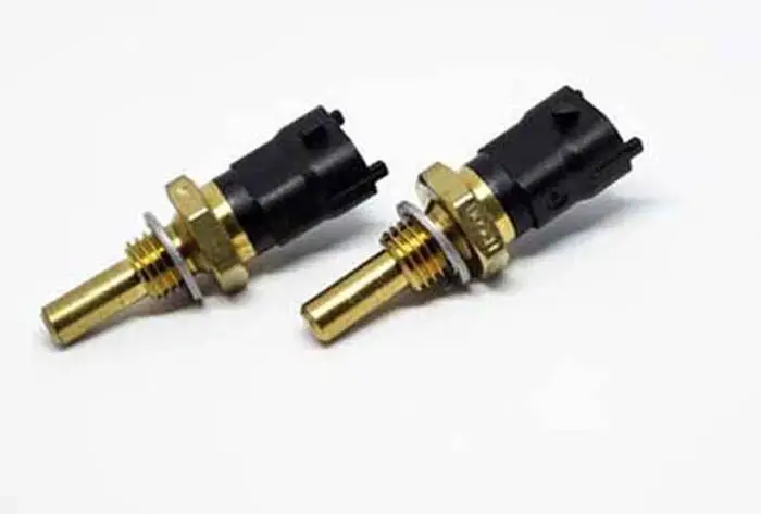
There are three types of coolant temperature sensors: 1-wire, 2-wire, and 3-wire sensors. Each type of sensor has a different wiring diagram and is used in different engine control systems.
1-wire coolant temperature sensor
A 1-wire coolant temperature sensor is the simplest type of sensor, and it is commonly found in older cars. This sensor has only a single wire, which is used to ground the sensor.
2-wire coolant temperature sensor
A 2-wire coolant temperature sensor is more common in newer cars. This type of sensor has two wires: one wire is for the ground, and another one is for the signal.
3-wire coolant temperature sensor
A 3-wire coolant temperature sensor is the most advanced type of sensor and is typically found in modern cars with more sophisticated engine control systems. This sensor has 3 wires: 1 wire is for the ground, 1 wire is for the signal, and 1 wire is for cluster mounted temperature gauge.
Coolant Temperature Sensor Wiring Diagram
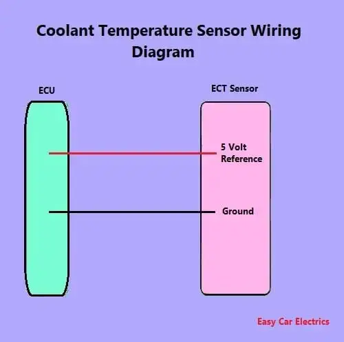
In this powerful article, we will be more general than specific. Here you will learn a general ECT sensor wiring diagram. For your specific car’s ECT sensor wiring diagram, you should check your car owner’s manual for authentic wire color.
The wiring image of the coolant temperature sensor is based on year, make, and model. The color of the engine coolant temp sensor varies and is color-coded according to the make and model. Below are the 1, 2, and 3-wire engine ECTS wiring diagrams.
Related Post: How to Replace a Coolant Temperature Sensor
I . Single Wire Coolant Temperature Sensor Wiring Diagram
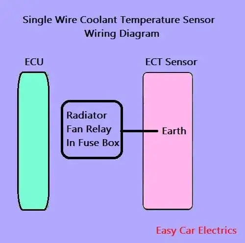
A single-wire coolant temp sensor has only one wire, which goes to the radiator fan relay.
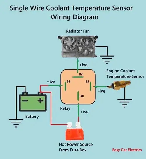
When the temperature of the engine coolant gets hot (almost 98 degree Celsius), the single-wire coolant temp sensor’s resistance decrease (almost 0) and creates a connection of ground from the engine body.
This ground connector goes radiator’s relay 85 terminals in the fuse box to activate the relay, and the current starts to flow from the fuse box to the radiator fan, which ultimately turns ON the radiator fan.
Related Post: How To Test Coolant Temp Sensor Wiring With Multimeter
II. 2 Wire Temp Sensor Coolant Temperature Sensor Wiring Diagram
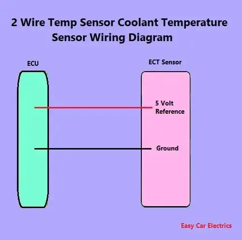
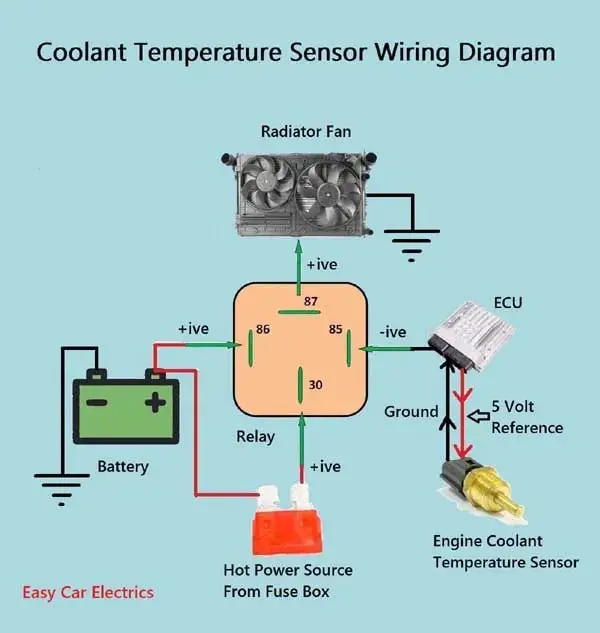
The Vast majority of ECT sensors are of 2-wire type. In a 2-wire coolant temp sensor, the sensor has two wires.
- 5-volt Reference Wire
- Ground Wire
The sensor gets both of its wires from the ECU.
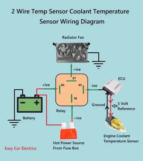
In a two-wire coolant temperature sensor, the ECU controls the radiator fan through the relay. The sensor does not have a direct connection with the radiator fan. The ECU takes the info from the coolant temp sensor and decides to turn the fan ON or OFF to act as a thermostat.
The ECU continuously monitors the temperature of the coolant, when it reaches almost 98 degrees Celsius; the ECU then orders the radiator fan by providing an earth signal to the radiator relay in the fuse box.
When the coolant’s temperature cools down, then the ECU shuts off the radiator fan by cutting the earth signal to the radiator relay in the fuse box.
Related Post: 9 Symptoms Of A Bad Engine Coolant Temp (ECT) Sensor
III. 3 Wire Coolant Temperature Sensor Wiring Diagram
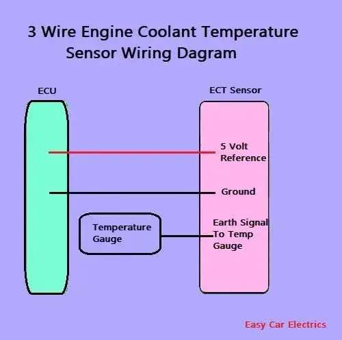
The three-wire coolant temperature sensor is superseded by a two-wire coolant temp sensor. A three-wire coolant temp sensor has the following three wires.
- 5 Volt Reference Wire
- Ground Wire
- Earth 1-Wire for Cluster-Mounted Temperature Gauge
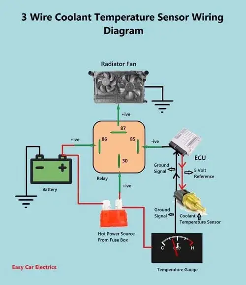
The two wires, a “5-volt reference”, and a “ground wire” go to the ECU, and the third wire “Earth 1-Wire for Temp Gauge” goes to the cluster-mounted temperature gauge by providing an earth link to the temperature gauge.
In three-wire coolant temp sensors, the ECU does not control the temperature gauge in the cluster. The coolant temp sensor provides an earth signal according to the temperature of the coolant. Higher the temperature of the engine’s coolant, the lower the resistance of the ECT sensor, and vice versa.
When the temperature of the coolant increases, the resistance of the sensor decreases, which sends high earth 1-wire to the temperature gauge, and you see the temperature gauge indicator fully turned to the hot indication.
Similarly, when the engine coolant temperature decreases, the sensor resistance also decreases, which sends low earth signal to the temperature gauge, and the indicator rests on the cool indication.
Related Post: Can A Bad Coolant Temp Sensor Cause Rough Idle, No-Start, Or Misfire
How to Properly Wire the Coolant Temperature Sensor in Your Vehicle
Properly wiring the coolant temp sensor in your vehicle is important for authentic temperature readings and efficient car performance. Follow these steps to ensure that your coolant temp sensor is wired correctly:
- Identify the type of coolant temperature sensor in your car. You can consult your car owner’s manual or a repair handbook to determine the type of sensor and its wiring diagram.
- Disconnect the black battery cable to prevent any electrical shocks or damage to the system.
- Locate the coolant temp sensor. The sensor is typically located on the engine block and is in contact with the engine coolant.
- Depending on the type of sensor, you may need to ground the sensor wire or connect it to a 1-wire and a reference voltage wire. Refer to the wiring picture for your specific sensor type to determine the correct wire links.
- Use a multimeter to test the sensor’s resistance and ensure that the wiring is accurate. The resistance values should correspond to the temperature of the engine coolant.
- Once you have verified that the wiring is accurate, reconnect the negative battery cable.
- Start your car and allow it to run for a few minutes to ensure that the coolant temperature readings are authentic and that the engine is running efficiently.
By following these steps, you can ensure that your coolant temp sensor is wired correctly and that your engine is running smoothly. Remember to consult your car manual or a repair handbook for specific instructions and diagrams for your particular make and model.
Conclusion
In conclusion, the 1, 2, & 3 Wire Schematic diagram of coolant temp sensor wiring is a helpful tool for understanding how to wire a coolant temp sensor. It offers all of the necessary information to ensure that the installation process is completed correctly and efficiently. This wiring diagram can be used by both novice and experienced installers. By following these diagrams, anyone should be able to install a coolant temperature sensor with confidence and success.
FAQs
The number of wires in a coolant temp sensor varies depending on the specific model and make of the sensor. Generally, most coolant temp sensors have between one and three wires. However, there are some models that have more or fewer wires. The best way to tell the authentic number of wires for a particular sensor is to consult the manufacturer’s instructions or specifications on youtube.
The coolant temp sensor measures the temperature of the engine coolant and acts as the sender it sends the information to the ECU. If the sensor is wired backward, it will still work, but the readings will be reversed. For example, if the coolant temperature is warm, the sensor will read cold. This is unlikely to cause any damage, but it will give the electronic control unit inaccurate information about the engine’s coolant temperature.
The TPS measures the position of the throttle and sends this information to the ECU. A faulty position sensor can cause issues with acceleration, stalling, and poor fuel economy. To diagnose a faulty, you can use a multimeter to determine the resistance of the sensor’s pins and compare them to the manufacturer’s specifications.
An aftermarket exhaust system can increase the horsepower of a 2500 series pickup truck by reducing back pressure and improving exhaust flow. When selecting a new exhaust, you should consider factors such as the material (e.g. stainless steel or aluminized steel), the design (e.g. cat-back or axle-back), and the manufacturer’s reputation for quality and performance. It’s also important to ensure that the new fumes system complies with local emissions regulations.
To replace the fuel pump on the right side of your car’s engine, you will need to remove the bolts that secure the fuel-pump to the engine block. Disconnect the electrical plug from the gas pump and remove the old pump. Then, install the new gas pump and thread the bolts back in place, ensuring a tight and secure fit.
Sign Up

