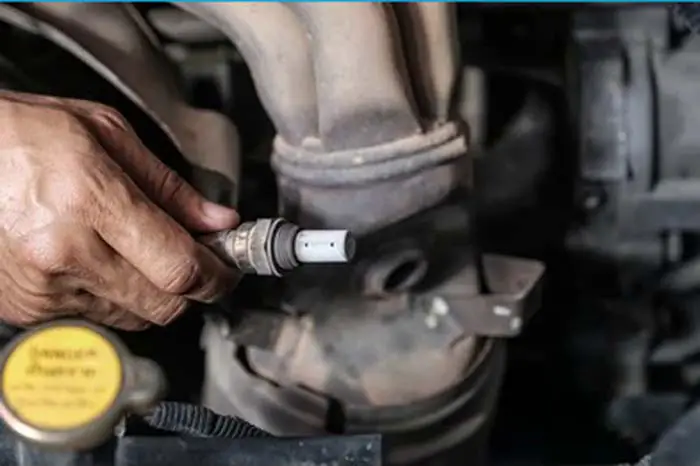
An oxygen sensor also called O2 Sensor or lambda sensor (λ) is an electronic sensor that measures how many oxygen molecules are present in the exhaust gas, which helps the ECU monitor the engine performance.
An oxygen sensor is a device in a car that helps to monitor the levels of oxygen in the exhaust system. Doing this, it helps the engine to run more efficiently and produce fewer emissions. The oxygen sensor is located in the exhaust system.
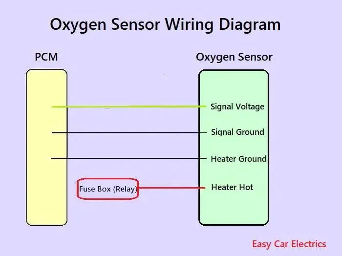
An oxygen sensor wiring schematic is a drawing that shows how the oxygen sensor is connected to the vehicle’s electrical system. The diagram will show the location of the oxygen sensor, the type of sensor, and the color of the wires. The diagram may also show the location of other sensors and components that are related to the oxygen sensor.
In this powerful guide, you will learn the wiring diagram of oxygen sensors such as 1, 2, 3, and four-wire o2 sensor wiring schematic.
Related Post: Cracking 3, 4, & 5 Wire Mass Air Flow Sensor Wiring Diagram Secrets
The Importance of Oxygen Sensors
The oxygen sensors, also known as the O2 sensors, are a critical component of a modern vehicle and industrial emission control systems. These sensors measure the amount of oxygen present in the exhaust gases produced by combustion engines or other combustion processes.
The importance of oxygen sensors lies in their ability to provide real-time feedback to the engine control module (ECM) or other control systems, allowing for precise fuel control. This helps to improve engine performance and fuel economy and reduces harmful emissions.
Without oxygen sensors, the ECM would be unable to accurately determine the amount of fuel needed for efficient combustion, leading to decreased fuel efficiency and increased emissions. In addition, malfunctioning oxygen sensors can cause a range of problems, including decreased engine power, increased fuel consumption, and increased emissions of pollutants.
The front sensor and rear sensor are part of the emissions control system, with bank 1 and bank 2 referring to the different sides of the engine (b1s1, b2s1), and the sensor is always monitoring the emission gases. If the sensor fails, it could trigger the check engine light (CEL) and generate a Diagnostic Trouble Code (DTC) that can be read with a scan tool to help diagnose the issue.
Beyond their use in automotive and industrial applications, oxygen sensor plays a crucial role in medical settings, such as in monitoring patients with respiratory conditions. emissions sensors can detect changes in the oxygen concentration in the blood, providing doctors with valuable information about a patient’s respiratory health.
Types of Oxygen Sensors
There are several types of oxygen sensors, including:
- Zirconia Oxygen Sensors: This is one of the most common types of oxygen sensors in automotive applications. They operate by measuring the difference in oxygen concentration between the emission gas and a reference air sample. Zirconia sensors are highly accurate and can detect small changes in oxygen concentration, making them ideal for use in emission control systems.
- Titania Oxygen Sensors: These sensors are commonly used in industrial applications, such as monitoring the oxygen levels in furnaces and boilers. They work by measuring the changes in electrical conductivity of a titanium dioxide film in response to changes in oxygen concentration. Titania sensors are rugged and durable, making them ideal for use in harsh environments.
- Wideband Oxygen Sensors: These sensors are used in modern vehicles with electronic fuel injection systems. They operate by measuring the oxygen concentration in the emission gas and providing a signal to the engine control module (ECM), which adjusts the air-fuel ratio for optimal engine performance and acts as a ratio sensor. Wideband sensors provide more precise readings than narrowband sensors, allowing for better fuel economy and lower emissions.
- Narrowband Oxygen Sensors: These sensors are used in older vehicles with carbureted engines. They operate by measuring the oxygen concentration in the emission gas and providing a signal to the ECM, which adjusts the air-fuel ratio. Narrowband sensors provide less precise readings than wideband sensors but are still effective in maintaining proper engine performance.
The type of oxygen sensor used depends on the specific application and the required accuracy and sensitivity of the measurement.
Oxygen Sensor Wiring Diagram
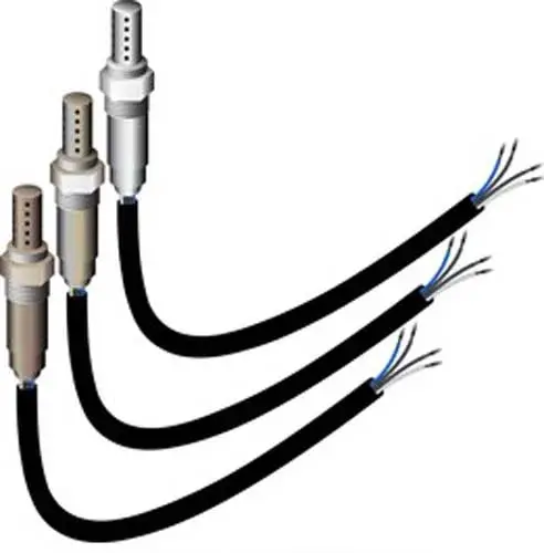
The wiring diagram of the oxygen sensor is different based on year, make, and model. It depends upon the manufacturer how they design the oxygen sensor wiring schematic. But, in this guide, I am more general than specific. I mean, I am giving you a general idea of how the emissions sensor wiring is designed.
For your specific make and model, you should visit your car owner’s manual. The color of wires will vary and color codes depend upon the brand of the sensor.
Related Post: What Is Oxygen Sensor In A Car
Heated Oxygen Sensor Wiring Diagram
The oxygen sensor does not provide a signal volt to the car computer until it gets hot, that’s why a heater is used to heat up the emissions sensor. Most cars equipped with OBD II has heated oxygen sensor.
The oxygen sensor equipped with a heater has an internal heater circuit that quickly heats the sensor to the operating temperature. This heater has a separate wiring circuit, which usually has two wires.
oxygen/emission sensors equipped with heaters mostly have 3 or 4 wires. Below are the three and four-wire heated oxygen sensor wiring schematics.
- 3 Wire Oxygen Sensor wiring schematic
- 4 Wire Oxygen Sensor wiring schematic
Related Post: 3 & 4 Pin MAP Sensor Wiring Diagram
3 Wire O2 Sensor Wiring Diagram
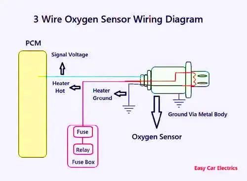
A three-wire emissions sensor has one wire for the sensing element, which goes to the Powertrain Control Module. This wire is a voltage signal wire means the voltage produced by the sensor will send to the car computer.
The remaining two wires are for the heater, in which one wire goes to the fuse and relays in the fuse box, and the 2nd-wire is earthed somewhere in the chassis. A three-wire oxygen sensor’s sensing element is earthed via a metal body to the exhaust manifold pipe.
4 Wire O2 Sensor Wiring Diagram
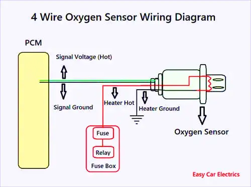
A 4-wire oxygen sensor or air-fuel ratio sensor wiring schematic is also called a universal O2 sensor wiring diagram. A four-wired oxygen sensor circuit has four wires, two wires for the heater circuit, and two wires for the sensing element.
The sensing element cords go to the Powertrain Control Module, in which one wire is signal ground and the second wire is signal voltage. Here sensor signal means the air-fuel ratio sensor sends the signals (electric potential) to the Powertrain Control Module.
The remaining two wires are for the heater circuit, which is hot and earth. The heater circuit earth wire is grounded somewhere in the chassis of the car. While the heater cables go to the fuse and relays in the fusebox. As you know sensor heaters consume a lot of currents, so battery voltage is usually supplied through a relay and a fuse.
Here you should remember, the heater circuit of the emissions sensor is controlled by the PCM or ECM through three different methods depending upon the car manufacturer. The oxygen sensor heater circuit is controlled by power (Hotwire), ground, or relay.
In some cars, the heater circuit’s earth wire is controlled by the Powertrain Control Module means the earth wire goes to Powertrain Control Module. And some car manufacturers control the heater circuit by power means the hot wire goes to the PCM.
In some cars, the heater circuit is controlled by the relay whereas the relay is controlled by the Powertrain Control Module means the relay’s earth wire goes to the Powertrain Control Module. The essence of controlling the heater circuit by the PCM or ECU is, to know the open or short circuit of the heater circuit by taking the feedback.
This is an Info
In every vehicle, the heater’s circuit is turned off by the Powertrain Control Module when the switch is ON and the engine is OFF to prolong the life of the sensor. And also in some cars, the heater circuit is disabled when it has an OBD II code.
This is an Info
A four-wire oxygen sensor has better experience than a three-wire emissions sensor because a four-wire oxygen sensor has a dedicated ground wire, rather than relying on the emission manifold as a ground.
Related Post: What Causes An Oxygen Sensor To Fail
Non-Heated Oxygen Sensor Wiring Diagram
When the car has started, the emissions/oxygen sensor does not produce voltage until it gets hot. Non-heated oxygen sensors rely on emission gases to bring them to the operating temperature.
Sensor without heater core usually has one or two wires, which go to the ECU. Below are the 1 and 2-wire non-heated emissions sensor wiring schematics.
- One Wire Oxygen Sensor
- Two-Wire Oxygen Sensor
One Wire Oxygen Sensor Wiring Diagram
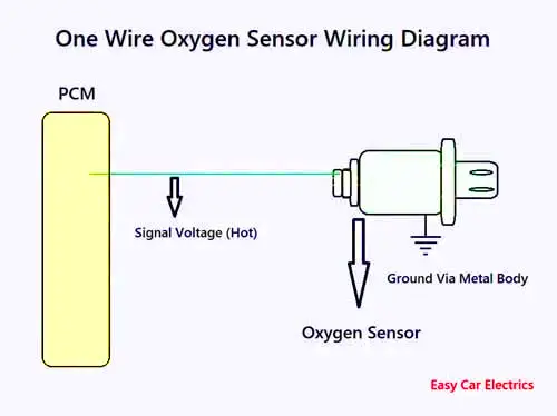
A one-wire oxygen sensor has one signal wire means a sensor voltage wire, which goes to the automotive computer. These kinds of sensors are earthed via the sensor’s metal body to the exhaust manifold pipe.
Related Post: Where Is The Oxygen Sensor Located
2 Wire O2 Sensor Wiring Diagram
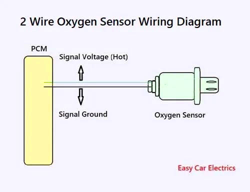
A two-wire oxygen sensor (02 sensors) has two wires, signal voltage, and earth. The voltage-signal wire connects to the automotive computer. It is the wire through which the emissions sensor sends the voltage to the computer. And the 2nd-wire is the earth, which also goes to the automotive computer (Powertrain Control Module).
Conclusion
Oxygen sensors play a crucial role in ensuring the efficiency of modern engine management systems. The four types of oxygen sensors – 1, 2, 3, and 4-wire – each have their own unique wiring schematic. By understanding these diagrams, you can diagnose and fix any issues with your engine’s emissions sensor. Whether you are a mechanic or a car technician, knowing the ins and outs of emissions sensors will help you keep your engine running smoothly.
Frequently Asked Questions (FAQs)
The wiring color of the oxygen sensor depends upon the make and model. Make and model will dictate which wires are used for what purpose. Usually, the white wires on an oxygen sensor are for the heater. The heater is not powered on all the time, but only when the temperature is too low for the sensor to function properly. The reason for this is that the emissions sensor measures the amount of oxygen in the emission gas. If there is too little oxygen, it means that the fuel mixture is too rich and needs to be adjusted.
If you unplug your O2 sensor, it will no longer be able to measure the oxygen content of the emission gas. This can cause the engine to run too lean or too rich, depending on the situation. If the engine runs too lean, it may not have enough power and may overheat. If the engine runs too rich, it will use more fuel than necessary and may produce excessive emissions.
Technically, the car is still drivable without an oxygen sensor, but it will not run as efficiently as it could. Without it, the car will run rough and sluggish. Cars are designed to run on a mixture of air and fuel, with the ideal ratio being 14.7 parts air to 1 part fuel. The lambda sensor is responsible for monitoring the level of oxygen in the emission gases and adjusts the air-fuel mixture accordingly. Without an emissions sensor, the car will still run, but the engine will be less efficient and the car will likely experience more wear and tears
When troubleshooting a faulty front oxygen sensor on a Toyota, it’s important to check both the wiring harness and the sensor connector. A faulty sensor can also cause fuel trim and DTCs issues, so it’s important to diagnose the issue correctly. To use a multimeter to determine if the sensor is bad, you can follow these steps: Start by disconnecting the sensor connection and setting your test meter to the resistance setting. Measure the resistance between the two heater wires. The resistance should be between 10 and 20 ohms at room temperature.
Sign Up

