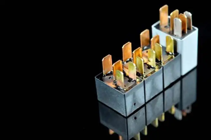
Do you know, that sometimes a relay warms up due to constant usage, causes electrical short circuits inside the relay, and stops the electrical flow?
When the relay cools, it starts the electrical flow again. A relay is a simple switch used to connect and disconnect the electrical circuit. It is used to switch multiple circuits at the same time using a single output.
If you want to gather information about car relay. Or If you are an automotive technician or a non-technical guy.
You came to the right place.
In this powerful guide, you will know what the relay is in a car, its construction, working, and many more things that are explained very easily.
You need to know that automotive relays have a big market. The demand for safety, luxury, and comfort in a car makes the automotive relay market grow bigger and it is estimated that by 2027 its market will grow up to 21.8 billion USD from 14.2 billion USD in 2019.

Related Post: Normally Open & Normally Closed Relay, Diagrams, Symbols With Pictures
What Is A Car Relay
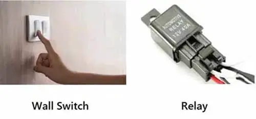
In most simple words we can say that a relay is a switch. It is the same switch we people have on our home walls turning the fan and bulb ON and OFF. Both switches are the same, they both make and break the circuits.
But, listen there is one difference and that is, the home switch is operated manually by hand while in automobiles, it is operated electrically by the output of various sensors and systems. We use relays to open circuits in vehicles instead of switches. So, a car relay is also called an electric switch or electromagnetic switch.
Related Post: How To Wire A 4 Pin Relay For Horn & Lights With Diagram: No More Confusion.
Who Invented the Relay
An American Scientist Joseph Henry is considered to be the inventor of the relay in 1835.
Uncovering Secrets of Car Electrical Relay Parts
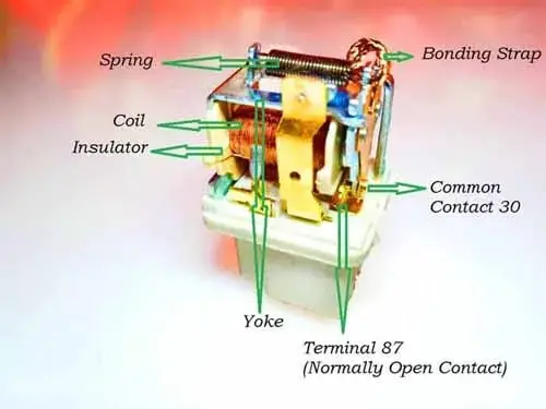
Car relays are composed of several components, including:
- Electro-Magnet: This is the core part of a relay and is responsible for creating the electromagnetic force that moves the contacts. It is typically made up of a coil of wire wrapped around a ferromagnetic core.
- Contacts: These are the electrical connections that open and close to control the flow of current depending on the input. They are typically made of a conductive metal such as silver or gold and can be either normally open relay contacts or normally closed relay contacts.
- Armature: This is the moving part of the relay that is attracted by the electromagnetic force of the electromagnet. It is typically a metal rod or plate that is connected to the contacts, and when the relay is energized, it moves to close or open the contacts.
- Common Terminal: This is the terminal on the relay that is connected to the electro-magnet and receives the low current signal that controls the relay.
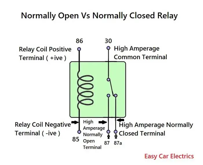
- Normally Open (NO) Terminal: This is the terminal on the relay that is connected to the normally open contact and carries the high current circuit when the relay is energized.
- Normally Closed (NC) Terminal: This is the terminal on the relay that is connected to the normally closed contact and carries the high-current circuit when the relay is not energized.
- Diode: A diode is an optional component that can be included in a relay to protect the relay and circuit from high voltage transients that may occur when the relay de-energizes.
- Capacitor: A capacitor is an optional requirement that can be included in a relay to suppress electromagnetic interference (EMI) that may be generated by the relay.
Construction Of Car Relay
The basic theme and construction of all electro-mechanical relays are the same. But, the design, pin arrangement, and size of these vehicle electrical components differ from one another.
A relay is made up of a small coil of wires wrapped around the central iron core. The coil is fixed on a small metal piece frame called Yoke. And a relay also has a movable contact which is supported by a spring. This spring activates the movable contact to its original resting position when the relay is de-energized.
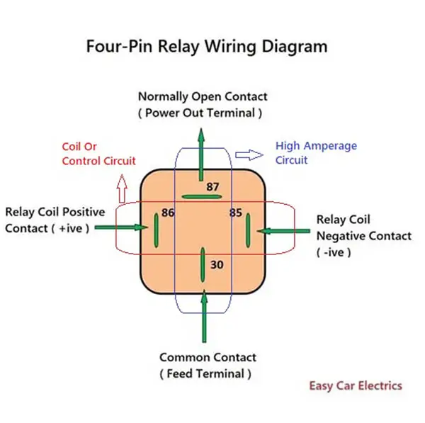
Moreover, there are two separate circuits in a relay. One circuit is for a coil circuit, which has two wires positive and negative power sources. And the second circuit of a relay is for a high amperage circuit.
When a relay’s coil circuit is supplied with voltage, it generates a magnetic field.
How A 12V Relay Works
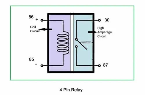
Car relay works on the principle of electromagnetism. When the current draw is directed towards the relay, it produces an electromagnetic field to attract the movable rod to make the connections. The relay is securely mounted in its designated location to ensure its proper functioning in the electrical system.
Now here I am explaining the science behind how an electromagnetic field is produced in the relay.
Consider a relay as two circuits. One circuit is called the Coil circuit (also called a low voltage circuit, a low amperage circuit, controlling circuit. The second half circuit is called a load circuit or high amperage circuit.
Remember that the load circuit is controlled by the coil circuit. When a current is applied to the relay’s coil circuit, a magnetic field is produced which attracts the movable rod and makes a physical connection to the high-amperage circuit. In this easy way, the relay is commonly used to switch various types of electrical parts in the vehicle.
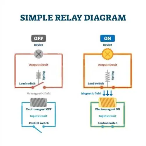
On the other hand, when the current is removed from the coil circuit, the movable rod moves back to its original resting position, causing it to disconnect the contact to reduce the current of the high amperage circuits.
If you were to look at a coil circuit, you would see an electromagnetic coil. Now here is the interesting point why there is a magnetic coil in a relay?
Wait? I will come to it later, now I want to help you understand electromagnetism. Look, there is a rule when you bring a magnet closer to the conductor, electricity is produced.
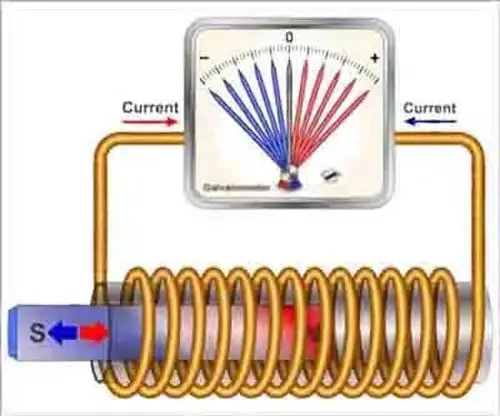
This happens with electricity when you apply electricity to a conductor, the magnetic field is produced.
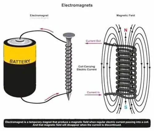
You might be wondering why a magnetic field is produced when a current goes in a conductor. The answer is, it is only known to Mother Nature.
However, scientist Michael Faraday discovered the relationship between the magnetic field and the electric field, which is also known as Faraday’s law.
According to Faraday’s law, any change in the magnetic field will produce an electromotive force (Electricity), and any change inflow of electric current in a conductor, will produce a magnetic field around that conductor. When the current flows to the relay’s coil circuit, an electromagnetic field is produced, which attracts the movable rod to connect the high-amperage circuit of the relay.
To sum it up, the purpose of the coil in a relay is to bring the movable rod closer to the load wire and make a high-amperage circuit connection.
This is an Info
The Coil Circuit controls the high Amperage Circuit of the relay.
This is an Info
The purpose of the coil in a relay is to bring the movable rod closer to the load wire and make a high-amperage circuit connection.
Car Relay Case Labeling
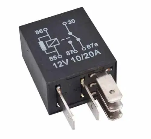
Some relays are marked on the case for identification purposes.
1. Voltage
A relay is marked up with 6, 12, and 24 volts.
2. Current
A relay is labeled with a current rating of 30/40 amp. Remember this current rating is for a high amperage circuit.
3. Relay Terminals
The numbers 85, 86, 30, 87, and 87a are marked on the plastic case of the relay along with circuit schematics.
Related Post: SPST Relay Vs SPDT Relay, Symbol, Wiring Diagram Explained
12V Relay with Diode
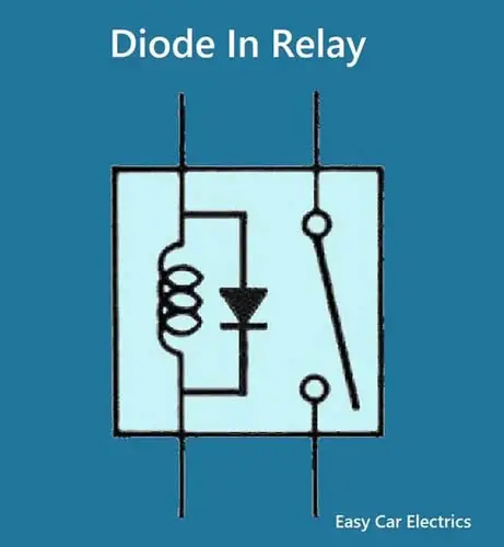
In an automotive relay, a diode has a special purpose that prevents high voltage spikes produced by the relay’s coil circuit to protect the sensitive electronic circuits.
When an energized relay is switched OFF, the magnetic field collapses, which produces high voltage spikes in opposite polarity across the coil circuit’s windings. This voltage is several hundred volts, but with a very low amp current, and will cause arching on switch contacts or can damage sensitive electric devices.
A diode is installed across the coil in a reverse-biased position and prevents damage by absorbing the high-voltage spikes when the relay is either open or closed. Thus, no current will flow through the diode, and electrical components are protected from damage.
The resistor in Automotive Relay Circuit
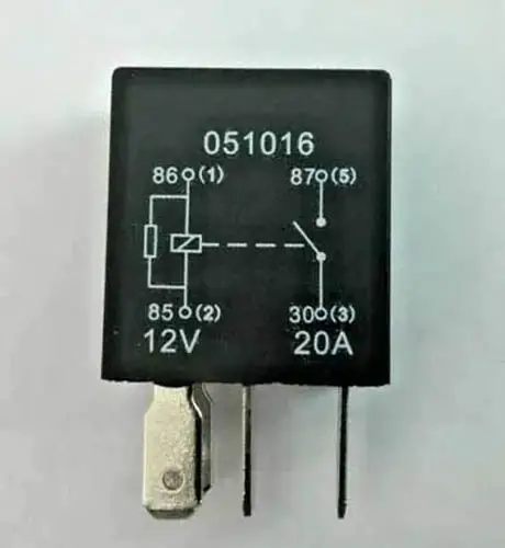
Sometimes a resistor is used in place of a diode. The function of the resistor in a relay is the same as in a diode to dissipate high voltage spikes. It absorbs high voltage spikes produced by the relay’s coil circuit due to the magnetic field collapse.
But, here is a problem, this configuration is not as suitable as a diode for stopping high-voltage beams. A little bit of voltage can leak through a resistor and can cause electrical damage.
But, here is also a piece of good news for you. The resistor has one advantage over the diode. It is not sensitive to polarity and you can connect either ground or hot power source to either terminal of the coil circuit (terminals 85 and 86).
Car Relay Applications And Uses
Car relays are an essential component in the electrical systems of vehicles. They are used to control high-current circuits with low current signals, allowing the vehicle’s systems to function efficiently and safely. The dual set of contacts in a 5 pin relay rapidly breaks and makes connections, providing precise control of electrical signals and power in various applications. Here is a list of common applications and uses of car relays:
- Starting The Engine: A relay is used to connect the battery to the starter motor, allowing the engine to start when the ignition key is turned.
- Headlights: Relays are used to control the high-current circuit of the headlights, allowing the low current signal from the headlight switch to turn the lights on and off.
- Fuel Pump: A relay is used to control the high-current circuit of the fuel pump, allowing the low current signal from the engine control module to turn the pump on and off as needed.
- Electric Fan: Relays are used to control the high-current circuit of the electric fan, allowing the low-current signal from the engine control module to turn the fan on and off as needed.
- Air Conditioning Compressor: Relays are used to control the high-current circuit of the air conditioning compressor, allowing the low-current signal from the air conditioning controls to turn the compressor on and off as needed.
- Power Windows: Relays are used to control the high-current circuit of the power windows, allowing the low-current signal from the window switch to control the movement of the windows.
- Power Seats: Relays are used to control the high-current circuit of the power seats, allowing the low-current signal from the seat controls to be sent and control the movement of the seats.
Some Helpful Tips
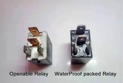
- Mostly moisture can get inside the relay making it prone to failure.
- Sometimes testing a relay, power is touched accidentally with the ground forcing it to blow the fuse. Be careful.
- Sometimes, a relay in the fuse box vibrates out due to being loosely fitted, which does not work properly, when the car goes on a bump the accessory loses work.
- Most relays come with a holder grip. Make sure to have clean and tight holder terminals.
- Sometimes too much current passing through a relay causes electrical connectors to “Stick” with each other due to heat. Power still goes on while the ignition is turned off.
- Some relays are openable while some are fully waterproof packs.
Frequently Asked Questions (FAQs)
n.c stands for “normally closed” and n.o stands for “normally open.”
A dual switch has two switch functions in one unit, allowing for multiple electrical circuits to be controlled.
Pin 87 is a common terminal in an electrical circuit, often used to connect a load or device.
86 are the coil pin. “86” is a code used in the automotive industry to indicate a certain part in the relay, in this case, a coil in the relay.
Yes, pin 87a can be integrated into an indicator light circuit to provide an additional control or output function.
A changeover switch in a passenger vehicle can be used to control the transfer of power between two different electrical systems, such as changing from low to high beams on the headlights.
I will be very happy if you subscribe to my newsletter and also share this article.
Sign Up

