Relays are widely used in a variety of applications, from simple switching circuits to complex industrial control systems. Understanding the differences between various types of relays can help you choose the right one for your application.
In this article, we will be comparing a single-pole single-throw, and a Single-Pole double-throw Relay, and discussing their features, functions, diagram, symbols, and applications.
Related Post: Purpose Of a Relay in a Car
What Is Relay
A relay is a switch that is used to turn on or off a circuit. It is operated by an electromagnet that is activated by a current flowing through the coil. The electromagnet then either opens or closes the switch, depending on the direction of the current. It is used to control multiple circuits by using a single trigger. The automobile relays are usually rated for a specific DC voltage, measured in volts. The different types of relay configurations are useful in different types of circuits.
Suppose you want an inactive circuit to activate, then you can use a single pole and single-throw relay. If you want the live circuit to be inactive, and activate another circuit at the same time, then you can use a single pole relay having dual throw.
Understanding Relay Terminals
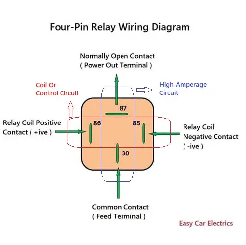
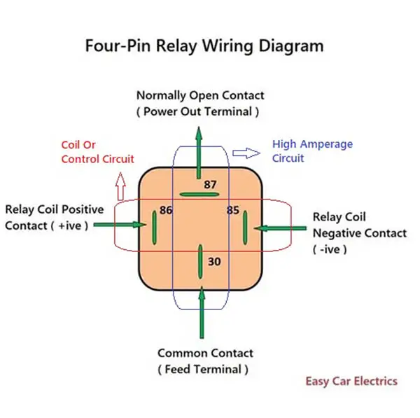
First of all, you should know the relay terminals and wiring schematics before understanding the single-pole and double-pole relays. A relay consists of 2 circuits, a coil, and high amperage circuit.
The electromagnetic coil circuit consists of two positive and negative terminals 86, and 85. terminal 85 is negative, while terminal 86 is a positive terminal. The high amperage circuit consists of two ends 30, and 87. end 30 is a common and power-in end, while end 87 is a normally-open and power-out end.
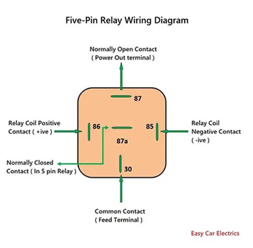
A five-pin relay has one extra end 87a in high amperage circuit. end 87a is used for circuits when power is required when the relay is inactive.
Related Post: Car Relay Guide
What Is Pole
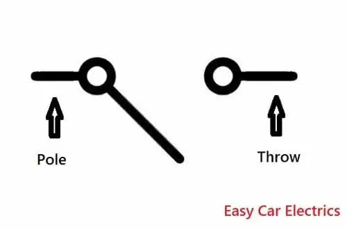
A Pole indicates the number of circuits controlled by a relay, a single-pole controls one circuit and a dual pole controls two different circuits. In the car relays, the pole refers to the shared terminal 30 of the relay.
What Is Throw
Throw indicates the set of contacts, single-throw means one contact, and double-throw means two contacts. In the car relays, the throw refers to the high amp circuits ends 87 and 87a.
This is an Info
Poles and Throws have nothing to do with the relay’s coil circuit. It is only concerned with the relay’s high amperage circuit. A single-pole means one shared terminal 30. A single-throw means the relay’s high amperage circuit’s terminal 87 and a dual throw means the relay’s high amperage circuit’s end 87 and 87a.
SPST Relay
A relay that is a single-pole single-throw is also called an SPST, or A Single-Pole Relay consisting of one pole and one throw. A single-pole single-throw has one pole, which is a shared end 30, and one throw, which is an end 87.
If a relay works to control one circuit for “One Operation” is called a single-pole single-throw. In fact, a four-pin relay is a relay that is a single-pole single-throw. Because this relay is activated to control one circuit (High Amperage Circuit ends 30 and 87) in a single operation. The contacts link the circuit when the relay is activated and disconnect when the relay is inactive.
Related Post: Starter Solenoid Wiring Diagram
SPST Relay Symbol
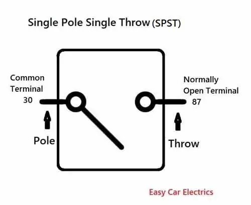
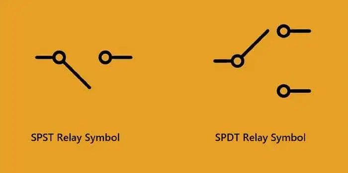
Single Pole Single Throw or SPST automotive Relay symbol represents a relay with a single contact that can either be one normally open or one normally closed. It has a total of four ends including the common terminal 30. Above, you can see the symbol of this relay.
SPST Relay Diagram
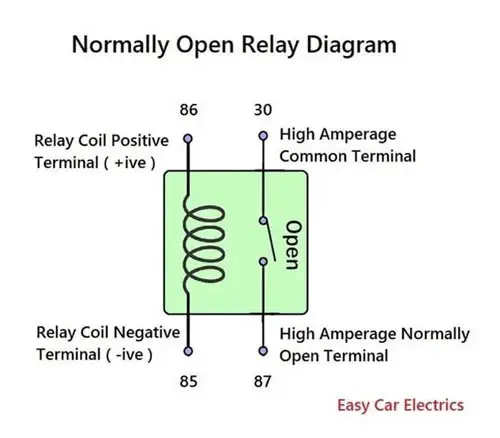
A normally open four-pin relay has a normally-open contact (end 87), which closes the relay contacts by energizing the relay and is called a single-pole single-throw NO (normally-open) Relay. A single-pole single-throw NO (normally-open) relay is mostly used in places like the car applications, such as air conditioners, radiator fans, horns, etc.
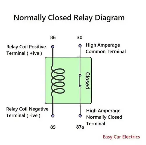
A normally closed four-pin relay has a normally-closed contact (end 87a), which opens the contacts by energizing the relay is called a single-pole single-throw normally-closed (NC) Relay. If you see the above normally-open and normally-closed relays, the relay control the high amperage contacts (Opens and Closes) in one operation, that’s why it is called a single-pole relay with a single-throw.
Related Post: Normally Open & Normally Closed Relay, Diagrams, Symbols
Features of SPST Relay
- Has one normally open contact
- The simplest type of relay
- Used in low-voltage applications
- Has a low power consumption
- Easy to operate
Applications of SPST Relay
single-pole single-throw relays are commonly used in low-voltage applications such as:
- Automotive lighting
- Small appliances
- HVAC systems
- Security systems
SPDT Relay
This relay has a single pole with dual throw also called SPDT, or double pole relay consisting of one pole and two throws. A single-pole double-throw has one pole which is end 30 and two throws which are end 87 and 87a.
When a relay controls 2 circuits in “One Operation” is called Single Pole dual throw (SPDT). A double-pole relay connects one circuit (ends 30 and 87) and disconnects another circuit (ends 30 and 87a) at the same time in one operation, that’s why it is called a single-pole relay with the dual throw.
SPDT Relay Symbol
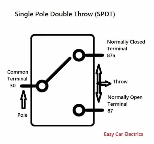
It has a total of five ends. Two for the coil circuit and three for the high amperage circuit. This relay has two terminals in which one end is normally-open (NO) and the other one is normally-closed (NC) at the same time. Above you can see the symbol of this Relay.
Related Post: How To Wire A 4 Pin Relay For Horn & Lights With Diagram
SPDT Relay Diagram
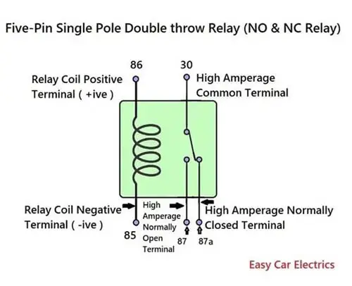
Practically, a five-pin relay is called Single-Pole dual throw because It controls two circuits (Contact 30 and 87) and (Contact 30 and 87a) in one operation. A five-pin relay has one common control end 30 and two contacts 87 and 87a.
When the relay is de-energized, ends 30 and 87a have connectivity. By energizing the five-pin relay, the common end contact 30 shifts from end 87a to 87, making the connection between ends 30 and 87.
Features of SPDT Relay
- Has one normally open contact and one normally closed contact
- Used in high-voltage applications
- Has a higher power consumption than the SPST relay
- More complex than the SPST relay
Applications Of SPDT Relay
single-pole double-throw relay-switches are commonly used in high-voltage applications such as:
- HVAC systems
- Elevator control systems
- Industrial control systems
- Power distribution systems
- Communications equipment
- Aerospace and defense systems
- Automotive applications
This is an Info
If a relay controls one circuit in “One Operation” is called an SPST type of relay. If a relay controls 2 circuits in “One Operation” is called an SPDT relay and if a relay controls three circuits in “One Operation” is a Single-Pole Triple Throw (SPTT) relay.
Conclusion
In conclusion, relays are crucial components that are used in a wide range of applications. By understanding the different types of it, one can make an informed decision on which type of relay-switch is best suited for their specific needs. The article compares single-pole single-throw and single-pole double-throw relays, their functions, wiring schematics, and symbols. The features of single-pole single-throw relay-switch, including their one normally open contact, make them ideal for applications like air conditioners, radiator fans, and horns in cars.
FAQs
Voltage is used to energize the coil in a relay, causing it to change state and switch the circuit.
A DPDT relay is a Double Pole relay with dual throw, which means it has two pairs of contacts that can be switched. When the relay is de-activated, one set of contacts is open and the other is closed. When the coil is energized, the state of the relay changes and the contacts switch to their opposite state.
To determine the continuity of the circuit when using a relay, you can measure the resistance across the coil when the relay is deactivated. If there is a complete path for current flow, a positive voltage or current should be present on one side of the coil and a negative voltage on the other. If you want to switch the relay to power a circuit, you need to ensure there is no open circuit and that the diode output is working correctly.
Sign Up

