A starter solenoid is an electromagnetic switch that produces a magnetic field to connect and disconnect the battery to the starter motor assembly. It is a huge switch, which works as a bigger relay to turn ON and OFF the starter motor assembly.
The solenoid works on the principle of electromagnetism. It has three terminals or connections on the back of the solenoid cap.
If you want to know the starter solenoid wiring diagram in simple words. This page explains very easily. On this powerful page, you will learn the solenoid wiring, especially the 3 pole wiring schematic for the starter solenoid in understandable language, so that you know what wires go to the starter solenoid.
Related Post: Car Starting System, Diagram, Working, Components, Function
Basic To The Starter
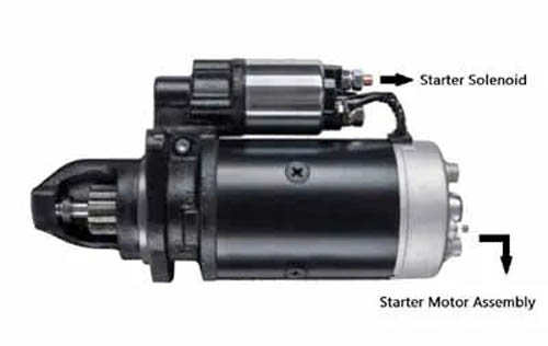
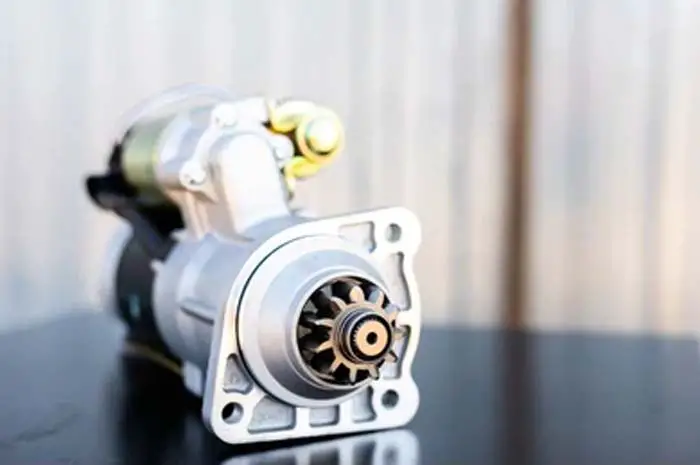
Numerous individuals frequently encounter confusion distinguishing the starter motor from the starter solenoid. The starter comprises pivotal components: a robust starter motor assembly and a strategically positioned solenoid. The starter motor assembly, a substantial cylindrical unit, serves as the powerhouse for engine cranking.
In contrast, the solenoid, a compact cylindrical component situated atop the starter motor assembly, plays a decisive role in establishing and disrupting the electrical linkage connecting the starter motor assembly to the battery. This distinction is crucial for comprehending the intricate workings of the automotive starting system.
Related Post: 6 Complete Starter Solenoid Parts, Functions & Working
What is Starter Solenoid in A Car
In the automotive context, a starter solenoid stands as a pivotal electromechanical switch, meticulously designed to initiate engine startup. This ingenious device achieves its functionality by delivering an electric current to the starting motor. Comprising two primary elements, it boasts an electromagnet activated upon current passage, working in tandem with a plunger. The plunger, in turn, meticulously completes the circuit, engaging seamlessly with the cranking motor. This intricate interplay of components underscores the indispensable role of the starter solenoid in the seamless ignition process of the automobile engine.
The Purpose of Starter Solenoids
The indispensability of the starter solenoid in vehicle operations cannot be overstated, given its pivotal role as an electromechanical relay. Its primary function revolves around establishing a crucial connection between the battery and the starting motor, a fundamental prerequisite for initiating the engine. This electrically controlled linkage ensures the unimpeded flow of current, serving as the catalyst for motor energization and the commencement of the combustion process. Consequently, the absence of this critical component would render a car incapable of starting, underscoring the irreplaceable role the starter solenoid plays in the ignition mechanism.
Starter Motor Parts
The starter motor is a vital component of the ignition system in an internal combustion engine. Here are its key parts:
- Commutator: Connects current from the brushes to the armature windings. The brushes ride on the commutator.
- Brushes: Provide current to create an electromagnetic field in the armature.
- Pinion gear: Connects to the armature shaft to turn the engine’s flywheel.
- Overrunning clutch: Prevents overspeeding and burnout.
- Planetary gear set: Helps turn the engine’s flywheel with less strain on the starting motor.
- Field coil or permanent magnet: Produces rotational force with the armature.
- Solenoid: Acts as a switch to turn the starting motor on and off.
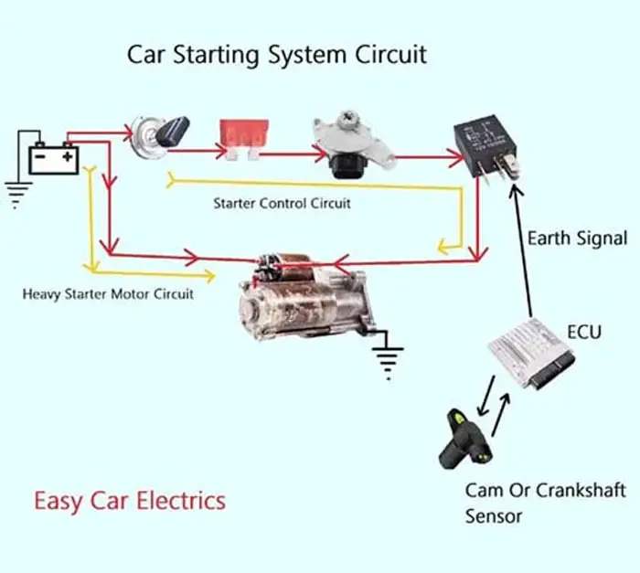
How Does a Car Starting System Work
The car’s starting system converts battery electrical energy to mechanical energy, activating the starter motor and initiating the engine’s first cycle. The ignition switch sends current to the starter fuse and safety switch, which triggers the solenoid. This causes the armature to spin and turn the starter gear, drawing a large amount of battery current.
The solenoid energizes the starting motor assembly, including the armature, commutator, brushes, pinion gear, overrunning clutch, lever fork, and planetary gear set. The starter’s pinion gear meshes with the flywheel, turning it to start the engine. The one-way clutch disconnects the starting motor armature from the engine flywheel ring gear to prevent overspeeding and burnout once the engine starts.
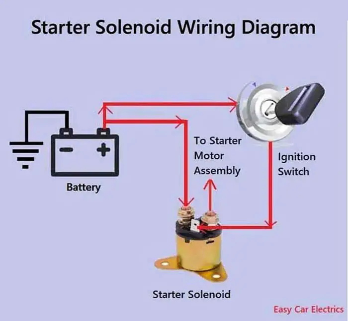
Starter Solenoid Wiring Diagram
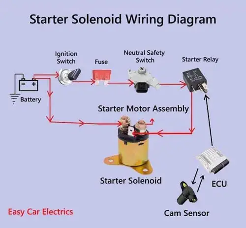
The starter solenoid wiring diagram is very easy, don’t worry. I am here to explain it quickly. A solenoid has three terminals/connections, one small pin-type connection, and two thicker bolt-type connections.

The small pin-type terminal/connection is called the “S” terminal. The “S” terminal links with the ignition switch circuit. This circuit is called the starter control wire, which controls the starter solenoid and links the ignition wire to the starter solenoid. The ignition switch sends the current to the starter solenoid through the fuse, then to the neutral safety switch, then to the starter relay, and finally to the solenoid.
The starter solenoid’s one thicker connection is the input terminal means the battery’s positive power source enters the solenoid through this terminal, and the second thicker connection is the output terminal, which goes to the starting motor assembly.
When you turn the starter switch key, it initiates the current flow from the starter switch to the starter fuse, then to the neutral safety or clutch pedal safety switch, then to the starter relay in the fuse box, and finally to the solenoid “S” terminal. The camshaft sensor provides DATA to the ECM or PCM. The ECM or PCM decides to send the signal to the starter relay to activate it.
When the starter relay is activated, it sends the current to the solenoid pin-type “S” terminal. When the “S” terminal receives the current, it pulls the starter’s plunger inside the solenoid making the connection between the two thicker terminals, and the current starts to flow directly from the battery to the starting motor assembly.
Related Post: 11 Parts Of Car Starter Motor & Functions
3 Pole Starter Solenoid Wiring Diagram
A 3-pole starter solenoid is usually also called a 3-terminal starter solenoid. It is the same solenoid we have discussed above. A 3-pole solenoid has three connections at the back of the solenoid cap, one small terminal, and two thicker terminals.
The small terminal is called the “S” terminal, which stands for signal means the starter switch signals the solenoid for activation through this terminal.
The other two terminals of the solenoid are thicker and larger in size, in which one large terminal is a feed terminal and is connected to the battery-positive power source. The second thicker terminal is the output terminal and is connected to the starting motor assembly.
Related Post: Types Of Starter Motor: Direct Drive & Gear Reduction Starter
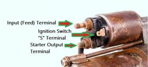
What Wires Go To The Starter Solenoid Terminals

The starter wiring diagram is no more a mystery. It is very easy. If you don’t know what wires go to the starter solenoid. Here is a quick illustration.
- The Pin-types “S” terminal goes to the Ignition Switch.
- The Bolt-type Feed Terminal goes to the battery-positive power source.
- The Bolt-type Output Terminal goes to the starter motor assembly.
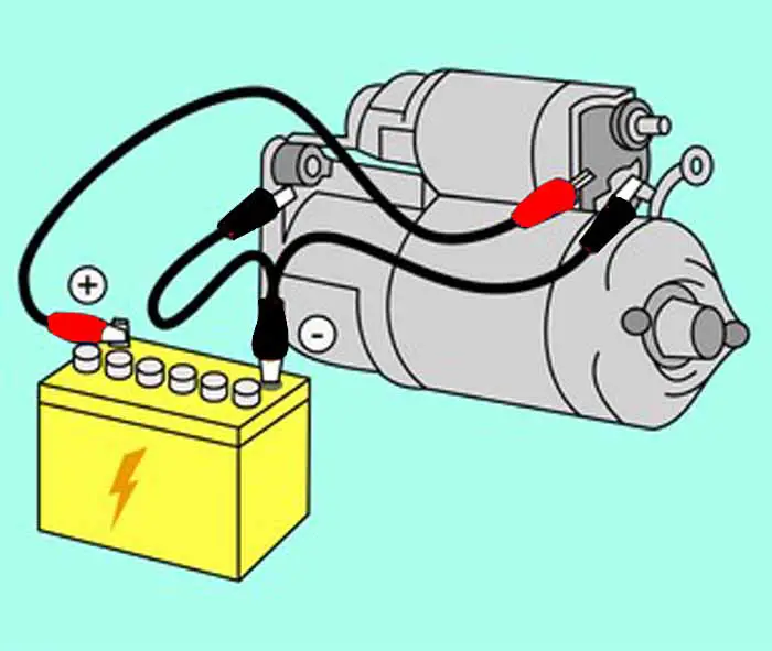
How to Wire a Starter Solenoid
Installing a solenoid requires three types of wire: the positive wire from the car battery, the wire going to the starter, and the thin pair of wires from the starter switch circuit. The positive wire from the battery is connected to the solenoid’s positive terminal. Then, one of the thin wires from the starter switch circuit is connected to the smaller metal stud terminals on the starter relay. Finally, a wire is usually connected from the solenoid to the starting motor. These connections should be made in accordance with the manufacturer’s instructions to ensure proper operation and safety.
Related Post: How To Wire A Starter Solenoid In 5 Min (With Diagram)
Troubleshooting Faulty Starter Solenoids
In order to ascertain whether a solenoid is operating at its optimal capacity, one must first assess the functional integrity of the device. Additionally, it is important to conduct an inspection of the physical integrity of the solenoid, ensuring that there are no major visual indicators of wear or damage.
- Listen for a Clicking Sound Coming From the Starter Motor: If you hear successive clicking and grinding noises when you turn the ignition key to the start position, it is likely a sign that the solenoid is bad and needs to be replaced.
- Unhook the Wires Across the Solenoid: Unhook the wires that go across the solenoid and turn the ignition key to the “run position. Listen to the solenoid: if it clicks, proceed to further test.
- Engine Doesn’t Crank or Start: If the starter solenoid switch is connected and your car does not turn on, it is likely that the solenoid is failing to transfer power and turn the crankshaft and needs to replace the solenoid.
- Intermittent Operation: If your car starts sometimes and not others, it is because sometimes the starter motor turns and the other time doesn’t. It is likely a sign of a failing solenoid.
- Your Vehicle Labors to Crank or Cranks Slowly: If your vehicle labors to crank or cranks slowly, it is likely due to the battery not having enough power to fully engage the solenoid and turn over the engine flywheel.
- Starter Fails to Engage: If the starter engages but does not disengage when you let go of the key, the solenoid is likely bad and the starter may suffer significant damage as a result.
Conclusion
In conclusion, the 3 pole circuit diagram for the starter solenoid provides a clear and concise illustration of how to wire a starter solenoid. It is an easy-to-follow guide that can help you save time and money when installing a new car starter. This guide can also be used for troubleshooting purposes, aiding in identifying any potential issues with wiring prior to installation.
Frequently Asked Questions (FAQs)
A typical starter solenoid has three wires, one wire goes from the solenoid to the starting motor and the two wires come to the solenoid from outside. One wire comes to one of the larger terminals from the battery, and the other wire comes from the starter switch. The solenoid is essentially a big electromagnet that closes a circuit between the battery and the starting motor. This allows current to flow to the starting motor, which then starts the engine.
A starter solenoid is a device that helps to engage the starting motor in a vehicle. The solenoid is usually mounted on the starter itself, and when the key is turned to the “start” position, it activates the solenoid which then closes a circuit between the battery and the starting motor.
A solenoid must be grounded in order to function properly. Without a ground wire, the solenoid will not be able to complete the starting circuit and provide the necessary power to start the engine. It is grounded via the starting motor.
A 4-pole starter solenoid typically has four connections: two connections are used for the high-current circuit and the other two are the low-current connections. The terminals are typically labeled “B” or “Battery,” “S” or “Start,” “I” or “Ignition,” and “R” or “15A.” The “B” or “Battery” terminal connects the solenoid directly to the positive battery cable. The “S” or “Start” terminal is the hot wire from the power supply. The “I” or “Ignition” terminal is connected to the starter. Finally, the “R” or “15A” terminal is connected to the starter switch. Some solenoids may contain only three connections, and the “R” terminal is then grounded through the mounting hardware.
Sign Up