Do you know what the start system means?
A car start system is a system, which starts your car’s engine and enables you to travel.
If you want to know more about the car starting system, its diagram, working, components, and functions. You are on the right page. Below is complete, comprehensive, practical, and effective information about the car starting system.
On this powerful page, you are going to learn the car starting system diagram, components, functions, and working explained in easy-to-understand language.
Related Post: Car Electrical System Basics, Vehicle Electrics, Function, Working, Diagram
Car Starting System
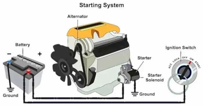
The car starting system is a crucial system for the car. It is based on converting the chemical energy stored in the battery into electrical and then mechanical energy in the starter motor.
The starter motor’s job is to start the engine. An internal combustion engine cannot start itself, it must be cranked at some speed (about 50-100 RPM for a gasoline engine) for a couple of firing strokes until the engine runs on its power.
The starter is a large electric current consumer and runs very fast, if it is not turned on and off on time, it can damage and discharge the battery. A system is used to operate the starter motor properly on time to prevent the starter from being damaged and gets saved the battery power, called starting system, whose job is to start the car with the greatest possible efficiency.
The latest model cars have starting systems based on an integrated control method by the electronic control unit (ECU). The ECU-based starting system has the potential to be used for real-time condition monitoring and fault diagnosis of vehicles.
How Does A Car Starting System Work:
The starting system works on the principle of converting electrical energy into mechanical energy. It converts the electrical energy of the battery into starting the engine. So, the function of the starting system is to provide an engine start with the greatest possible efficiency.
All internal combustion (IC) engines cannot start themselves. It needs external help to set the engine in motion before it can power itself. Thus, a starter motor is used to initiate the first working cycle of an IC engine. As soon as, the engine has started, then it relies on inertia from each working cycle to initiate the next working cycle, so the cycle resumes and the engine continues to start running.
Furthermore, the starting system consumes a lot of current from the battery to energize the starter motor. This is the reason; the starter circuit requires a large diameter cable to carry the current.
Related Post: 11 Parts Of Car Starter Motor & Functions + Working
Starting System Diagram

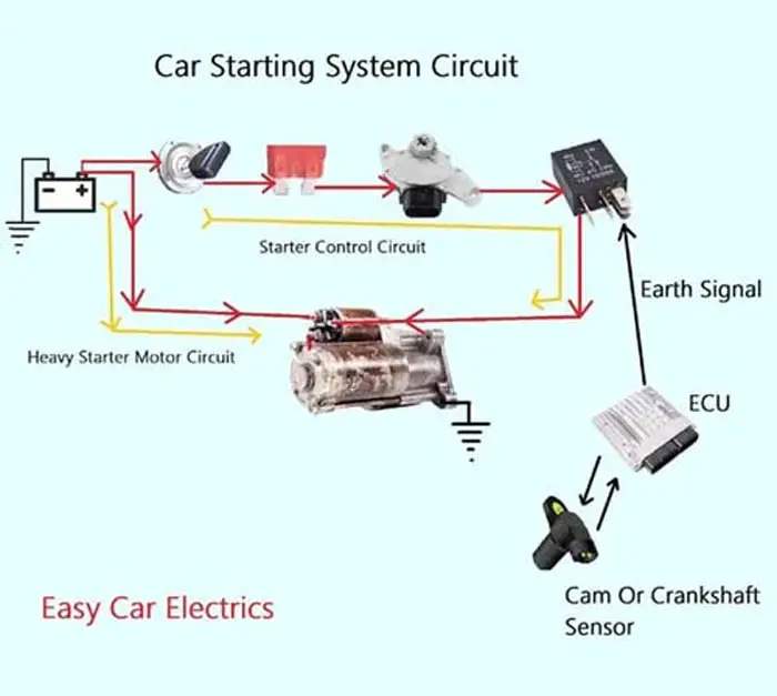
Here you should remember that we cannot use a large diameter lengthy cable from the instrument panel to the starter motor. As it would be so long that will increase the voltage drop and also cost. To avoid such a voltage drop and long route of a large diameter cable, the starting system circuit is divided into two sub-circuits.
- Starter Control Circuit
- Heavy Electric Starter Motor Circuit.

Using a large diameter cable from the instrument panel to the starter motor can increase the voltage drop and also cost. The control circuit goes on a long route from the instrument panel to the starter solenoid ignition switch terminal. This circuit only turns on and off the starter solenoid that acts as a bigger relay.
And the solenoid further energizes and de-energizes the starter motor assembly. The control circuit consumes less power and has normal gauge cables. It starts from the ignition switch and goes to the starter fuse, then to the starter safety switch, the circuit then continues from the safety switch to the starter relay in the fuse box and finally to the starter solenoid.
The second circuit is a heavy electric starter motor circuit that draws heavy current directly from the battery through a heavy cable and is controlled by the solenoid. This circuit goes directly from the battery through a large diameter cable to the starter solenoid and then to the starter motor assembly.
When the ignition key is turned to the start position or a start/stop button is pushed in the keyless car, the current flows from the ignition switch to the starter fuse and then to the starter safety switch.
Here I want to talk a little about starter safety switch variation. The automatic and manual transmissions use two different types of safety switches placed in different locations. In a manual transmission, the safety switch is located at the clutch pedal end and its contacts are open, and will only be closed when the driver presses the clutch pedal. When the pedal is pressed, the current starts to flow to the starter relay, as a result, the relay is activated.
This is an Info
When the ignition key is turned to the start position or a start/stop button is pushed in the keyless car, the current flows from the ignition switch to the starter fuse and then to the starter safety switch.
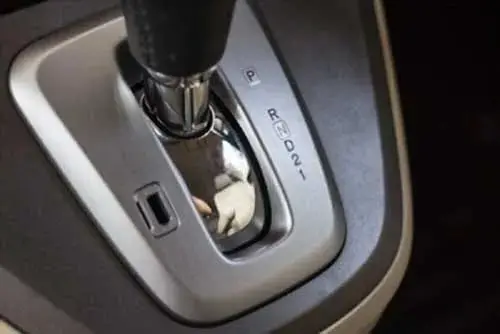
On the other hand, in an automatic transmission, the park/neutral safety switch is located under the gear shift lever or at the gearbox case. In an automatic transmission, the Engine Control Unit (ECU) sends an earth signal to the relay to energize it. The ECU will only allow an earth signal to the starter relay when it detects the safety switch in the park or in neutral.
The Engine Control Unit (ECU) takes input from the cam or crankshaft position sensor and some other sensors and calculates them together, through which the ECU decides to send an earth signal to the starter relay and fuel pump relay. So, when the starter relay is activated, a large amount of current goes from the battery to the starter solenoid.
The solenoid is an electromagnetic switch, which acts as a bigger relay allowing and disallowing a large amount of current from the battery to the starter motor assembly. As the solenoid is energized, it also energizes the starter motor assembly.
The starter motor assembly consists of many parts such as armature, commutator, brushes, pinion gear, overrunning clutch, and planetary gear set. The commutator takes the current from the brush and sends it to the armature. Where the magnetism is created and as a result, the starter motor turns.
The planetary gear set is used to increase its torque to overcome the resistance of the piston’s up-down movement. As the armature starts to rotate, meanwhile the pinion gear is pushed forward by the solenoid to mesh with the engine flywheel. Thus, the engine is cranked and gets started.
If, the engine has started and the flywheel speed is increased compared to the starter motor pinion gear while the pinion gear is still meshing with the engine flywheel. Then, the overrunning clutch comes into action. It disconnects the starter motor armature from the flywheel ring gear. This is done to protect the armature from overspeeding and burnout.
As you can see, the starting system is complex; it is the combination of two circuits and many components. I hope you would have understood. I tried my best to help you understand in an easy language.
Related Post: Types Of Starter Motor
Starting System Components And Functions
Below is a comprehensive explanation of starting system components and their functions.
- The Battery
- Ignition Switch
- Starter Relay
- Starter Safety Switch
- Starter Motor
1. The Battery
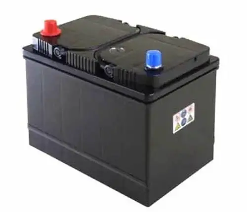
The battery also known as a Power Bank is starting system’s component. A car battery is an electrochemical device that stores the current in chemical form and converts it into electrical current when needed. The battery is the heart of the car’s electrical system and is usually placed in the engine compartment.
It provides electrical current to all the circuits and components when required once the engine has started and the alternator is able to produce the current then the current is supplied by the alternator. The battery also provides additional current when the current demand is greater than the alternator can supply.
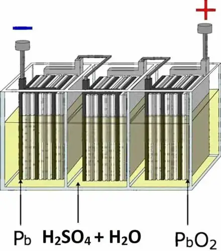
There are many types of car batteries, but the most common type is the lead-acid battery. It is named a lead-acid battery because it contains lead (Pb) plates inside the battery submerged in sulfuric acid (H2SO4).
The liquid inside the battery is called the electrolyte, which is a mixture of sulfuric acid (H2SO4) and water (H2O). Indeed, a fully charged lead-acid battery consists of 40 percent sulfuric acid and 60 percent water. The lead plate and electrolyte create a chemical reaction, which releases energy and gives us the electric voltage and current.
Here you should remember one crucial point a car battery does not store electric current directly. It stores the energy in the chemical form and converts that chemical energy into electrical energy (Electric Current) when needed.
No batteries in the world can store electric current directly, all batteries store the electric current in another form other than electrical energy. The lead-acid battery is a rechargeable battery.
But it is not a deep cycle rechargeable battery which means the battery should not be discharged more than 70 percent, which is harmful to the health of the battery and can reduce its lifespan. And it should be noted, when the electric current is supplied to the battery, its chemical reaction is reversed, and we call it that the battery is recharging.
Remember, hydrogen gas emits while charging the battery, which is highly vulnerable to sparks and flames, so be careful while charging the battery. Moreover, the battery is measured in cold cranking amps (CCA) to determine the battery’s ability to start the engine at cold temperatures.
It is because, in a cold climate, the chemical reaction in the battery slows down, which reduces the battery strength and minimizes the ability to produce maximum current.
That is why a good battery is considered the one, which cranks the engine for 30 seconds at 0 F temperature while still maintaining a voltage equal to or higher than 1.20 volts per cell or 7.2 volts for the whole battery.
This is an Info
The car battery does not store electric current directly. It stores the electric current in chemical form and converts that chemical energy into electrical energy (Electric Current) when needed.
This is an Info
The hydrogen gas emits while charging the battery, which is highly vulnerable to sparks and flames, so be careful while charging the battery.
Functions Of The Battery
- The battery in the car has the following four functions.
- Provides the current to all the circuits and components when the engine is off
- Acts as an electrical current reservoir
- Supplies extra current when the electrical requirement is higher than the alternator produces
- Acts as a stabilizer, it regulates potentially- damaging voltage spikes while the engine is running
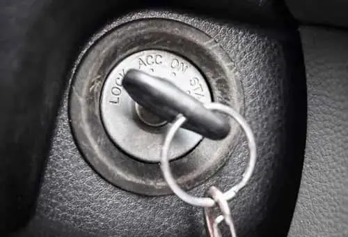
2. Ignition Switch:
The ignition switch is a starting system component. A general definition of a switch is making and breaking the electrical circuit. In vehicles, the ignition switch makes and breaks all electrical circuits. It is the gateway of the electrical circuits and distributes the electrical power throughout the car where needed.
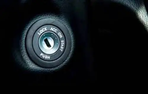
The ignition switch has basic four positions, but the newer cars have an extra built-in lock position to lock the steering wheel. Following are the ignition switch positions.
Lock, Off, Accessories, Run/ON, Start,
Key rotary ignition switches all positions are “detented” except the “starting” position. This means, by turning the switch, the switch will remain stuck in that position until the driver turns back the key. In older cars, the key rotary ignition switches were mounted on the instrument panels.
On the other hand, in late-model cars, the ignition switches are mounted on the steering column to lock the steering wheel from rotating, so that the car cannot be stolen, especially when the key is out of the switch. Nowadays, the ignition switch is superseded by a “Start/Stop” button in the latest model cars. Now below is an explanation of every single position of the ignition switch.
Ignition Switch Positions
Below are the five positions of the ignition switch.
- Lock Position
- Off Position
- Accessory Position
- Run/ON Position
- Start Position
Lock Position: This is the position in which the key is inserted but not yet turned. In the lock position, all the electrical circuits are off (no current flow) and the steering wheel is locked. Some cars have the lock and off positions built in together in the same position. The key can only be extracted when it is in the lock position.
Off Position: It is the default position, in the Off position, all the electrical circuits are “off” (no current is supplied), and the steering wheel is free to turn, but the key cannot be extracted.
Accessory Position: This is the first turn. In the accessory position, the current is supplied to all the accessories (components) except starting and ignition system. In this position, the current is allowed only to accessories such as radios, cigarette lighters, windows, etc.
Run/ON Position: This is the position in which the key remains, once the engine has started. In the Run/ON position, all the electrical systems are activated except starting system. The current is supplied to all the components including, the fuel pump, fuel injectors, various sensors, ABS motors, SRS airbag, dash lights, and many other components, except starting system’s circuit.
Conversely, the vehicles equipped with a Push/Start button may combine the accessory and Run/ON position with the first push of the button.
Start Position: This is the last position of the key rotary ignition switch. It is a spring-loaded returnable position, which returns to the Run/ON position when the key is released. In this position, the current is supplied to only the starting and ignition system, and the current is cut off from all the accessories.
That’s why the radio, windows, and other accessories stop working while the engine is being started. It is to ensure the maximum cranking capacity of the battery.
Function Of The Ignition Switch
The function of the ignition switch is based on controlling the flow of electric current. The ignition switch controls the current to all the electrical circuits in the car and distributes it where it is needed.
3. Starter Relay:
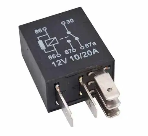
This is another important part of a car starting system. A relay is an electromagnetic switch that connects and disconnects an electrical circuit by using a small amount of current to control a large amount of current.
The starter motor uses 250+ amps of current, which is a large amount of current. You cannot control such a huge amount of current directly from the ignition switch. It could damage the ignition switch. That’s why a relay is used in the starting control circuit to control a large amount of current by using a low amount of current.
Starter Relay Wiring Diagram
Below is the starter relay wiring diagram.
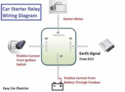
A starter relay consists of two circuits, a low amperage circuit, and high amperage circuit. The low amperage circuit also called the coil circuit, which draws less current. The coil circuit has two terminals 85, and 86. Terminal 86 is a positive contact and is connected to the ignition switch via a starter safety switch. And terminal 85 is a negative contact and is controlled by ECM or PCM in automatic transmission.
In a manual transmission, terminal 85 is directly connected to the earth connection in the fuse box. (Just as the fusebox has positive connections, similarly the fusebox has earth connections too). This causes the relay to energize and sends a high amount of positive current from terminal 30 to the starter solenoid through terminal 87 of the high amperage circuit in the relay.
Hence, the starter motor activates and gets the engine cranked. Here remember, some cars do not use a starter relay, in this kind of starting system, the current goes from the ignition switch to the fuse and then to the starter safety switch, from there, the current directly goes to the starter solenoid bypassing the starter relay.
These are the two types of starting systems, one is with a starter relay starting system, and the second one is without a starter relay starting system.
Function Of The Starter Relay
The function of the starter relay is to control a larger current by using a smaller current. The ignition switch cannot bear controlling the high amount of current, as it would damage the ignition switch. Therefore, a starter relay is used to consume less current and controls a high amount of current to the starter motor.
Related Post: Car Relay Guide & How A 12V Relay Works
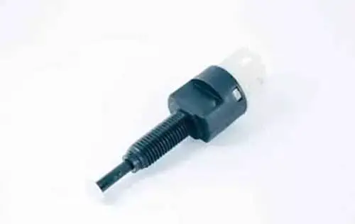
4. Starter Safety Switch
This is another important component of the starting system. The starter safety switch is a part of the transmission range switch that prevents the starting system operation when the car is in gear (In Automatic Transmission), or the clutch pedal is not pressed (In Manual Transmission).
The purpose of the starter Safety Switch is to not allow the car to start in gear as it would cause the car to jerk forward or backward accidentally. The Starting circuit will only be completed, when the automatic transmission is in the Park or Neutral position, or if the car has a manual transmission when the clutch pedal is depressed.
Manual and automatic transmissions have separate safety switches.
- Clutch Pedal Safety Switch (In Manual Transmission)
- Park Neutral Position Switch (In Automatic Transmission)
1. Clutch Pedal Safety Switch In Manual Transmission
In a manual transmission, the safety switch is located on the Clutch pedal end, and starting circuit will only be completed when the clutch pedal is depressed. This safety switch is an open switch, and its contacts are only closed when the driver presses the clutch pedal.
In a manual transmission, the clutch pedal only allows a hot power source to the starter relay. The starter relay’s coil circuit, terminal 85 is already earthed in the fusebox. The only hot wire goes to the starter relay’s terminal 86 when the clutch pedal is pressed, and the relay is energized.
2. Park Neutral Position Switch (PNP Switch)
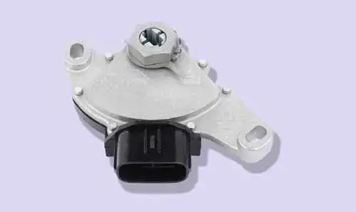
The Park Neutral Position Switch is a safety switch that prevents the starting system from operating when the automatic transmission is in any gear other than park or neutral. The park neutral position switch gives information to the Engine Control Unit (ECU) about gear positions, and in which gear the transmission is.
When the ECU detects that the gear is in the park or Neutral position, then the ECU sends an “Earth signal” to the starter Relay terminal 85 and the Relay is energized. If the ECU does not detect the gear in Park or Neutral position, then it will- not energize the starter relay. The park neutral switch is located either below the gear shift lever or beside the gearbox or some cars have it inside the transmission case.
A Park Neutral Position Switch is of two types.
- Mechanical
- Shift by wire
- Mechanical Park Neutral Safety Switch
In mechanical shift transmission, a cable or linkage is used to connect the gear shift lever to the park neutral switch at the gearbox.
- Shift by Wire Neutral Safety switches
In the “Shift by Wire” shift transmission, the transmission position changes through electronic control, without any mechanical linkage between the gear shift lever and gearbox. This shifting can be operated by a lever, touch screen, or joystick.
Working Operation Of The Starter Safety Switch
Starter safety switches are installed in the line of starting circuit. These switches prevent the car from accidentally starting whenever the driver turns the ignition key to the start position or pushes a start/stop button, current goes from the ignition switch to the starter fuse, then to the starter safety switch.
If the gears are automatic, then the current will only flow to the starter relay when the gear shift lever is in the park or neutral position. If the gears are manual, then the current will only flow to the starter relay when the clutch pedal is depressed. As, when the relay is energized then the current starts to flow from the battery to the starter. Hence, the starter is activated, and the car is cranked.
Function Of The Starter Safety Switch
The function of the starter safety switch is to prevent the car from an accidental start-up with the car in the gear or clutch not depressed, as it can damage the transmission by jerking forward or backward.
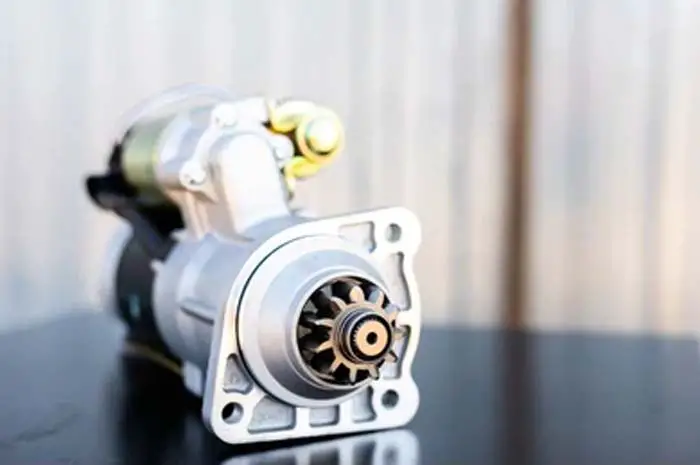
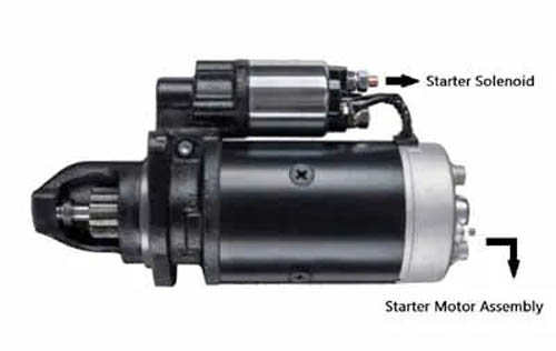
5. Starter Motor
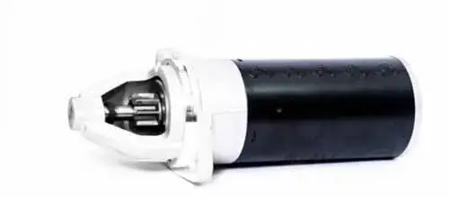
The starter motor is an essential part of the starting system. It is mounted on the back of the engine casing or on the transmission housing where the engine and transmission meet. The starter motor is an electro-mechanical device that converts electrical energy into mechanical energy in I.C engines.
A starter consists of a solenoid and a motor assembly. A solenoid is an electromagnetic switch that engages and disengages the battery to the starter motor assembly. It also functions as a bigger relay, which works on the principle of using a small current to turn on a bigger current.
The starter motor assembly consists of many parts such as armature, commutator, brush, pinion gear, overrunning clutch, etc. All parts get combined and have a working starts motor assembly.
Working Operation Of The Starter Motor:
When the ignition key is turned to the start position, the current flows to the starter fuse, then to the safety switch. From the safety switch, the current flow to the starter relay and finally to the starter solenoid.
This current energizes the solenoid and also activates the starter motor. The pinion gear transfers the starter motor rotation to the flywheel ring gear. The planetary gear set increases the torque of the pinion gear. At the end, when the engine has started and the driver releases the key, the starter motor de-energizes.
Function Of The Starter Motor
The function of the starter motor is to create torque to rotate the engine flywheel and gets the car cranked.
The starting system uses two types of circuits (wiring harness).
- Control Circuit
- Starter Heavy Circuit
The control circuit uses almost regular gauge wirings and goes from the ignition switch to the starter solenoid. This circuit draws less power as it controls the starter solenoid.
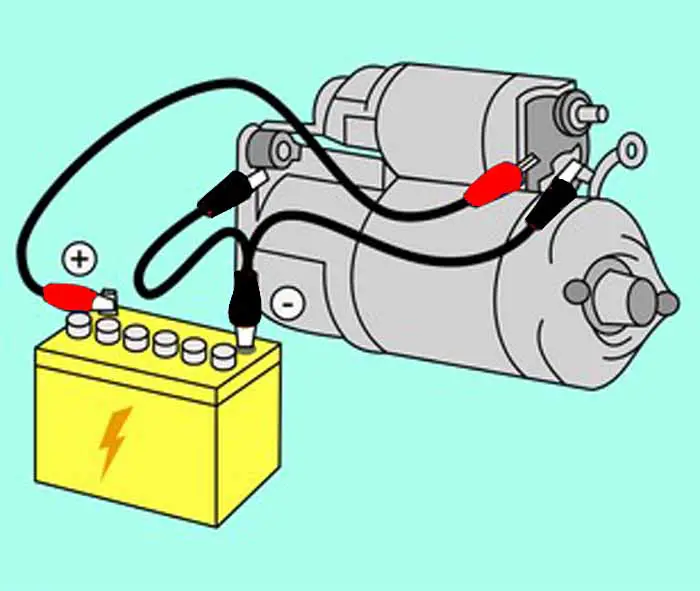
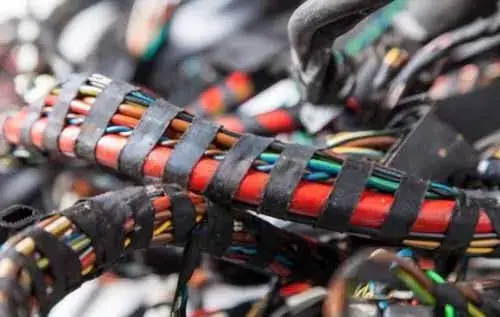
On the other hand, the second circuit is a heavy starter circuit; it is a positive cable of large diameter, multi-stranded, used for providing a large amount of current from the battery positive terminal to the starter motor.
Sometimes, it goes hidden from the battery, tapped together with other wiring harnesses to the starter motor. The starter cable usually becomes rusted with age and usage, which causes increases in the voltage drop and decreases the current flow to the starter motor.
It is recommended to replace the cables when it is corroded as it can give problems in starting the car. Usually, a battery cable will last anywhere from 50,000 to 100,000 miles.
Related Post: How to Test a Starter Motor with Multimeter without Removing
Sign Up