In the early time, most of the vehicle’s circuits were simple, containing a few basic circuits such as lighting, wiper, etc. Over time the vehicle’s circuits got updated, which increased its complexity. And the electrical system’s understanding became complicated and hard to understand.
If the electrical system is approached logically, it can become no more a headache. In this guide, the basics of an electrical system especially for beginners are explained in easy words to understand.
In this amazing and powerful article, you will learn the basics of a car’s electrical system, vehicle electrics, diagrams, working, parts, and basic terminologies, which are practically used in a car’s electrical systems. I am hundred percent sure, by reading this article you will be able to have a thorough grasp of the car’s electrical system.
Car Electrical System
For beginners it is essential to know the basics of a car’s electrical system and how a car electrical system works, so below is the explanation of a car’s electrical system and how it works.
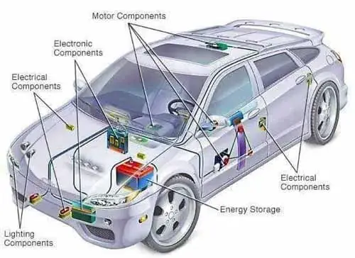
The car’s electrical system is composed of a wiring harness and electrical components. It consists of several smaller sub-electrical systems such as an ignition system, charging system, starting system, fuel system, lighting system, etc, which work together harmoniously.
In all sub-electrical systems, one thing is a must, and that is the need for voltage. Along with it, the electrical system of vehicles makes communication of the electrical components to its module, which is integrated throughout the car in length and width.
The car’s electrical system is a bit like your body’s blood circulatory system. The primary function of your blood is to provide oxygen and nutrients to the body’s cells and tissues. Similarly, the primary function of the electrical system is to provide voltage to all the electrical components in a vehicle.
This is an Info
The car’s electrical system is composed of a wiring harness and electrical components. It works by providing voltage to the component, which is necessary to operate the electrical components.
Related Post: Car Starting System, Diagram, Working, Components, Functions
Vehicle Electrics
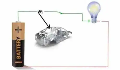
The vehicle electrical system is the system of electric wiring and parts in a vehicle. The vehicle electrics interconnect all the car’s electrical parts with each other by carrying electric current and voltage to all the parts such as various computers, sensors, actuators, motors, gauges, power windows, radio, headlights, sunroof, starter motor, and many other electrical components in the system. All the electrical component receive voltage from the battery and returns it to the battery, through the car’s metal body.
The battery is the fundamental source of power in the vehicle’s electrical system that provides the electrical current to all electrical components when the engine is OFF. With the engine running, all the electrical components receive energy from the alternators. It is because the car’s alternator produces a higher current than the battery, so at the same time, the alternator can charge the battery as well as supply current to all other needs of the car while the engine is running.
How Car Electrical System Works
The car’s electrical system is a complex network of wires which work by providing voltage to the component, which is necessary to operate. The car battery provides the voltage necessary to start the engine, which in turn provides the power needed to run the car. The amount of voltage necessary to operate the component depends on the specific component.
The electrical system of your vehicle is made up of a series of interconnected parts that work together to provide power to the car. The battery is the source of power for the car’s electrical system. The alternator recharges the battery and provides power to the car’s electrical components such as the headlights, wipers, and radio.
Automotive Electrical System Function
The purpose of an auto electrical system is to generate, store and distribute voltage to all of the electrical components in the vehicle. The system is made up of a number of different parts, including the battery, alternator, starter, and various sensors and switches. All of these parts work together to ensure that the auto electrical system is functioning properly.
Sub-Systems Of Auto Electrical System
A car’s electrical system is composed of many sub-electrical systems. Below are the common sub-electrical systems which are explained in easy words.
- Charging System
- Ignition System
- Starting System
- Fuel System
1. Charging System
The charging system provides electricity to your car’s electrical system. It provides the current to your car’s electrical systems and components such as starting system, ignitions system, fuel system, Lighting system, radio, air conditioner, washer pump, etc.
The alternator is the main component of the charging system. It supplies the electrical charge to the battery and accessories.
The battery stores the electrical current and initially provides the current to the car’s electrical system when the engine is OFF. As the engine has been started, and the alternator starts to produce the electrical current, then the current starts to flow from the alternator to the car’s electrical system.
2. Ignition System
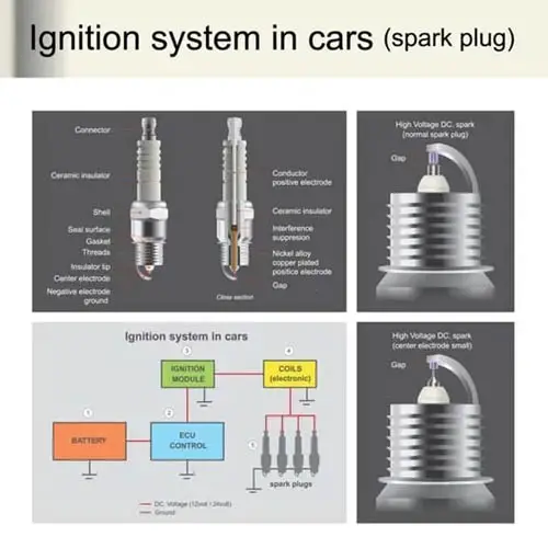
The ignition system is one of the electrical systems whose function is to provide a continuous spark to the spark plug in the compression stroke of the gasoline engine cylinders. Its job is to ignite the air-fuel mixture in a gasoline engine cylinder.
The ignition system consists of many components such as ignition coils, spark plugs, batteries, fuse, and relay. The ignition coil converts the normal battery voltage to a high-voltage pulse that goes into the engine cylinder to ignite the air-fuel mixture.
Diesel engines do not have the classic ignition system. In a diesel engine, the air-fuel mixture gets ignited when the air-fuel is compressed to such an extent that it heats up and ignites the air-fuel in the combustion chamber.
3. Starting System
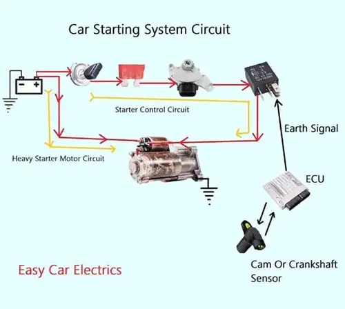
The starting system is an electrical system that works on the principle of converting electrical energy into mechanical energy. In the early days, the car was used to start with a mechanical hand crank. Later in 1912, the electrical starting system was introduced to start the car.
The function of the starting system is to provide an engine start. It helps start your car. The starter motor is the main basic component in the starting system. It uses electrical energy and converts it into rotational energy.
Related Post: 2 & 3 Wire Crank Sensor Wiring Diagram (With Pictures)
4. Fuel System
The fuel system is an electrical system that provides fuel to the engine cylinder. In the past, the fuel system was mechanical in which a mechanical fuel pump was used to send the fuel to the engine cylinder.
Due to advancements in technology, the fuel system started to operate electrically. The fuel tank stores the fuel that is pumped by the fuel pump through fuel pipelines to the engine cylinder. A fuel system consists of a fuel pump, fuel filter, inertia safety switch, fuse, and relay.
Related Post: Increased Fuel Consumption
Car Electrical Parts: Fuse, Relay, Battery, Alternator, & Starter Motor
The electrical system could include a fuse, relay, battery, alternator, starter motor, wiring harnesses, etc. Every part in a vehicle that operates electrically or electronically is called a vehicle electrical system’s part.
In the early generation of vehicles, the majority of components were mechanical and simple. With time, the vehicle’s parts got updated and upgraded which increased its complexity, and components started to operate electrically or electronically.
The reason for operating the parts electrically and electronically is for ease of operation and precision control. A car’s electrical system has hundreds of electrical and electronic parts. Below are explanations of major car electrical system parts.
- Fuse
- Relay
- Battery
- Alternator
- Starter Motor
1. Fuse:
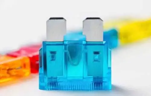
The fuse is the most essential part of the car’s electrical system. It is a safety device used to protect electrical wiring from damage in the event of a short circuit.
A fuse kills itself when the current exceeds its pre-determined current value. Ideally, every electrical circuit in a car should have a fuse to protect the circuit from damage in an overload event. The fuse’s working principle is based on the heating effect of the current. It is designed to blow into an overload situation and break the connection.
A fuse contains a metal element and two terminals encased by a plastic housing body. The metal element is a resistive material made from zinc, copper, or aluminum, which produces heat when the current flows through it.
When the current exceeds its predetermined current value, too much heat is produced in the fuse element, which causes it to blow the fuse. The fuse element is soldered to the fuse terminals. Fuses are located in the fuse box inside the cabin or outside the engine compartment. Some aftermarket circuits use an inline fuse.
Related Post: A Car Fuse Guide and Car Fuse Types
2. Relay:
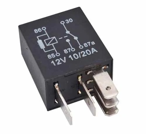
The relay is a very important car electrical system part. It can control many electrical circuits with a single trigger.
A relay is an electromagnetic switch used to connect and disconnect the electrical circuit. It is mostly used in heavy circuits, which consume a tremendous amount of current. The relay controls a large amount of current by using a small amount of current to avoid a burden on the wire.
The engine cooling fan uses a 12-volt relay to provide too much current to the cooling fan for maximum cooling. Similarly, the car air conditioner, ABS Motor, Headlight, starter motor, horn, etc use a relay to provide the maximum current to the vehicle component and avoid load on the wire. Relays are fitted alongside fuses in the fuse box.
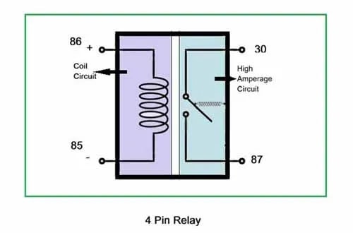
Usually, there are three types of relays used in the automobile industry that are three-pin, four-pin, and five-pin Relays. The four and five-pin relays are very common in a vehicle.
A relay has two circuits, a low amperage circuit (Coil Circuit) and high amperage circuit. Moreover, the pins of a relay are numbered 85, 86, 30, 87, and 87a according to the DIN standard. 85 and 86 pins are considered low amperage circuit (coil circuit) pins, while 30, 87, and 87a pins are considered high amperage circuits.
Related Post: Car Relay Guide & How A 12V Relay Works
3. Battery:
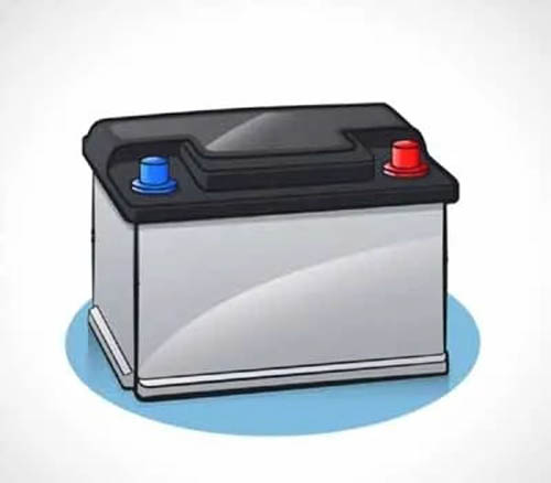
The battery is the heart and most necessary part of a car’s electrical system. It provides life to the electrical system. It is the basic source of electricity in the car’s electrical system. The battery also provides electric current through wires to all the electrical components.
The battery is an electrochemical device and a power bank, which stores the electrical current. It stores the electric current in chemical form and converts it into electrical (electric current) form when required. With the engine OFF, the battery provides the current to all the electrical circuits, including the ignition and starting circuit to start the engine. And when the engine starts, then the alternator supplies the current to all the electrical circuits.
The lead-acid battery is one of the most common batteries in the car. It contains lead (Pb) plates submerged in sulfuric acid (H2SO4).
The battery acts as a reservoir when the current demand is higher than the alternator produces, the battery provides additional current to the electrical circuits. Similarly, the battery acts as a stabilizer, it regulates damaging voltage spikes when the engine is running.
This is an Info
The battery is an electrochemical device and a power bank, which stores the electrical current. It stores the electric current in chemical form and converts it into electrical (electric current) form when required.
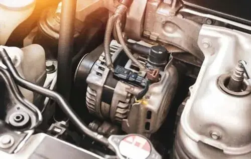
4. Alternator:
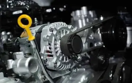
The alternator is one of the essential parts of the car’s electrical system. The alternator is an electro-mechanical device, which converts mechanical energy into electrical energy driven by the engine belt. The alternators produce AC current that is converted to DC current by a rectifier (Also known as a diode bridge which consists of six diodes).
The alternator provides electrical power to the car’s electrical system and battery while the engine is running. It initially needs the current to start producing the electric current. This initial current is known as excitation, in which the alternator is excited by the battery ignition switch through the exciter wire.
The type of alternator, which needs an excitation from the battery to start producing electric current, is called a non-self-exciting alternator. Some alternators do not need an excitation current, those types of alternators are called self-exciting alternators.
A fully charged battery gives almost 12.6 volts (with the engine off), and a good working alternator produces almost 14 to 14.6 volts.
Now you will think about why there is a huge difference between alternator and battery voltage production. The reason is simple, you might know that a voltage is an electrical pressure, and the current will only flow when there is a pressure difference or voltage difference between two points.
The alternator current will easily flow and charge the battery due to the high voltage production. If the alternator output voltage were set to produce 12.6 volts then there would be no voltage difference between the battery and alternator. And there would be no current flow between the alternator and the battery, hence the battery would not charge.
So, to charge the battery, the alternator must produce a higher voltage than the battery can provide to the car’s electrical devices.
This is an Info
The alternators produce AC current that is converted to DC current by a rectifier (Also known as a diode bridge which consists of six diodes). The alternator provides electrical power to the car’s electrical system and battery while the engine is running.
5. Starter Motor:
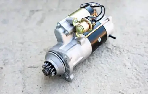
The car’s starter motor is an electrical component of the vehicle’s electrical system that helps in starting the car by turning the engine.
The starter motor, also called a starter or self-starter, is a device used to crank the engine. It converts electrical energy into mechanical energy in an I.C engine. It is mounted on the back of the engine casing or in front of the transmission housing.
The starter motor consists of several parts such as armature, commutator, brushes, pinion gear, overrunning clutch, field coil or permanent magnet, and planetary gear set. All these parts get combined, creating the starter motor. A solenoid fits on the starter motor assembly, which acts as an electromagnetic switch. The solenoid connects and disconnects the battery to the starter motor.
Related Post: 11 Complete & Detailed Starter Motor Parts & Functions
The Car’s Basic Electrical Terminologies And Definitions
Matter And Atom
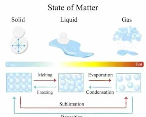
We will start our lesson with the matter as it is the basis of every material. In physics, everything around us whether we can see it such as Solid and liquid, or cannot see it like gases is considered Matter.
The matter is made up of Atoms. Atom is the building block of the matter. Everything you see around us, they are made up of the smallest particles called atoms. Atom is the smallest unit of matter. Our cars, home, mobile phones, clothes, etc all are called matter, which is made of the smallest particles called atoms.
Atom is a Greek word that means “Indivisible” because it was once thought that an atom is the smallest particle in the universe that could not be further divided but later it was discovered that an atom too can be further divided into smaller particles.
Proton, Neutron, And Electron
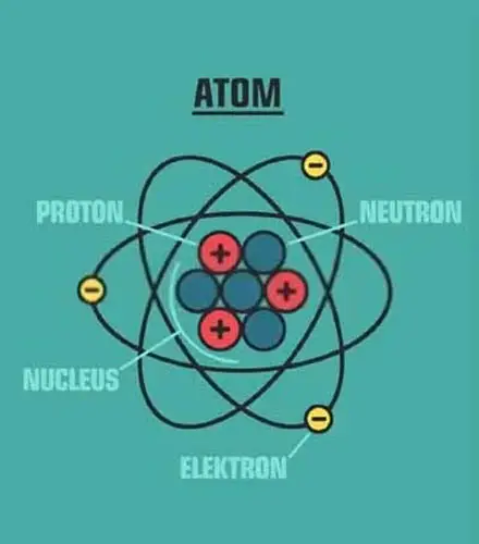
The atom itself is made up of three particles called Proton, Neutron, and Electron. Proton and Neutron reside in the nucleus at the center of the atom while electrons reside out of the nucleus orbiting the nucleus, similarly the planet in our solar system orbit the sun.
The electron is a negatively charged particle and can freely move from one atom to another atom when electrical pressure is applied. The movement of free electrons from one atom to another atom is called current.
This movement happens when electricity is applied to the conductor. Since the current is defined, as the flow of electrons in a circuit.
Whatever I have written above is all a theory presented by scientists. Nobody has seen matter, atoms, electrons, or protons with the naked eye. It is a theory that is accepted worldwide, you too should accept it this way.
Current
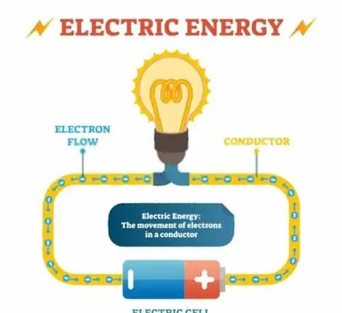
The flow of electrons is called current. The current is the basics of an electrical circuit. Without current, you cannot imagine a working electrical circuit. The symbol of the current is the uppercase letter “I”.
In fact, the electrons carry energy with them, which it utilizes in the circuit. When the electrons flow from the battery’s positive power source to a load of supposing bulb, the electrons lose energy in the form of light illumination in the bulb. And the energy-less electrons go back to the battery’s negative terminal through the metal frame.
Ampere is the unit for measuring the electrical current. One ampere is equal to One Columb. You need to know that one Columb is equal to 6.24 x 10¹⁸ electrons.
It is the billions of billions of electrons, which flow in one second in a unit area; this is the huge amount of electron flow in a second.
This is an Info
In fact, the electrons carry energy with them, which it utilizes in the circuit. When the electrons pass through the load it loses all the energy and the energy-less electrons go back to the battery’s negative terminal through the metal frame.
Types Of Current
There are two types of currents, Alternating current, and Direct current. Following are the explanation of both types of current.
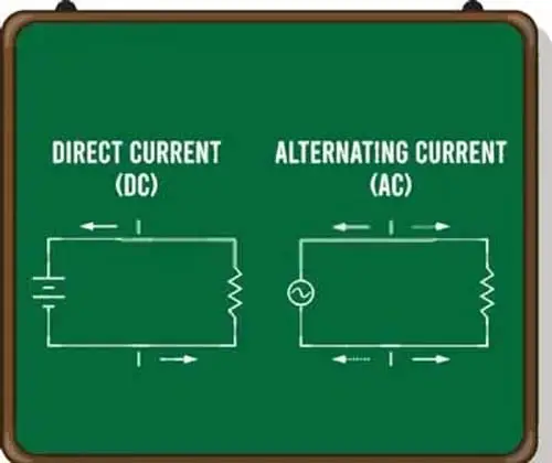
DC Current
Direct Current or DC is a current which goes in unidirectional in a circuit. It does not change its polarity. In an automobile, the direct current goes from the battery’s positive pole to the negative pole. Its polarity remains the same throughout the circuit.
DC current occurs when there are more electrons on one pole and fewer electrons on another pole. It is mostly used in the automobile industry. It can be stored electrochemically in batteries.
AC Current
An AC or Alternating Current is a current which changes its polarity in a circuit. The AC current flows in one direction and then in the opposite direction when the polarity is reversed, this is considered one cycle. AC current is not common in the automobile industry.
Voltage
Voltage is simply an electrical pressure (electromotive force) exerted by an electron on another electron. You can say that voltage is a force that pushes electrons around the circuit. The science behind the creation of the force is, this force is created by the difference between the quantity of positive and negative electrons on the battery’s negative and positive poles.
Suppose the battery’s negative pole has 170 electrons and the battery’s positive pole has 30 electrons, then 70 electrons will flow from the battery’s negative pole to the positive pole to balance the number of electrons on both sides.
In fact, there are billions of billions of electrons flowing from the battery’s negative pole to the positive pole in a fraction of a second. I am giving you an example to help you understand. This difference between both poles pushes the electrons from the battery’s negative terminals to the positive terminal. The more the difference is, the higher the pressure (Voltage) is.
More Voltage (Pressure) = More Electron Flow (Current)
More Electron Flow (Current) = Faster Starter Motor Will Spin and be Brighter The Headlight Bulb Will Be
The battery negative terminal has a huge amount of electrons, you can say billions of billions of electrons, while the battery positive terminal has a fewer amount of electrons. But here remember that in conventional current flow the electron flows from the battery’s positive power terminal to the negative power terminal. For further information, you can read the polarity topic on this page.
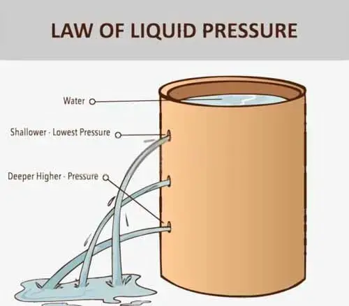
You can consider voltage as the pressure in a water pipe. If the water tank is fully filled with water, then the mass of all the water can cause a huge amount of pressure at the end of the pipe, this resembles that a fully charged battery will have high voltage. While a partially filled water tank will have less pressure at the end of the pipe, it means a discharged battery will have a low voltage. The unit of voltage is volt.
1 volt = 1 Joule ∕ Columb
Here for your reminder, the Joule is the unit of energy. A Columb is the unit of Current. One volt means that every Columb of charge can carry 1 joule of electric potential energy from the battery positive terminal to the battery negative terminal. Twelve volts means that every Columb of charge can carry 12 jouls of electric potential energy from the battery’s positive terminals to the negative terminal.
Voltage is also called the potential difference, which means it’s the difference in the amount of energy the charge can potentially carry from the battery-positive terminal to the battery negative terminal.
Most cars’ electrical systems and their components run on a 12-volt system, such as lighting systems, power windows, and other accessories. Many vehicles’ sensors use 5-volt voltage while the ignition coil uses high voltage almost from 5000 to 30000 volts to fire the spark plugs.
Some vehicles, especially military trucks use the 24-volt system, while newer cars have an additional 48-volt power system. Hybrid vehicles use a voltage of 140 to 300 volts.
This is an Info
There are billions of billions of electrons flowing (Electric Current Flow) from the battery’s negative pole to the positive pole in a fraction of a second.
Related Post: Oxygen Sensor Voltage: Why Voltage Fluctuates, Science-Based
Resistance
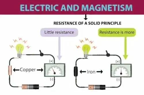
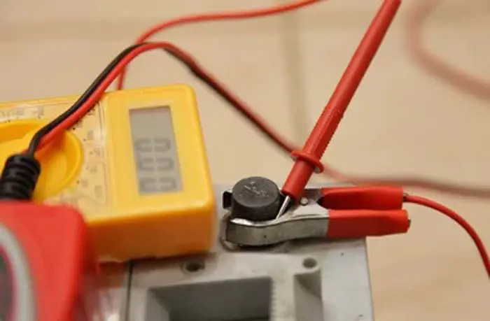
Electrical resistance or resistance is a material property to resist the flow of current in a circuit. Its unit is Ohm described by the Greek word Omega (Ω). It is measured by an Ohmmeter or a Multimeter having the function of an ohm checking.
All the circuits have some degree of resistance, some materials have a high level of resistance, such as rubber, glass, plastic, etc called an insulator, in which the current flow is the minimum. While some materials have a low level of resistance, like copper, silver, and gold, in which the current flow is high.
Some factors affect the resistance of a wire, while the current is flowing, such as temperature, length, corrosion, and size.
The electrical resistance of a wire increases with an increase in temperature, and vice versa. Similarly, the resistance of a wire would be greater for a longer wire, and lesser for a wire of a larger cross-sectional area. In a larger cross-sectional area, more electrons can flow due to low resistance, while in a lower cross-sectional area, fewer electrons can flow due to high resistance.
And in the last, corrosion is a significant element in increasing resistance. Corrosion builds up due to exposure to water, salt, and dirt. As for fault diagnosing, I have mostly experienced when a component does not work or works randomly, when I checked, the cause was the corroded connectors or corroded pin terminals of both male and female terminals.
This is an Info
Remember, never use an ohmmeter when the current is flowing in the circuit. it can kill the Ohmmeter.
Related Post: Testing The Resistance Of IAT Sensor With A Multimeter
Resistance In Materials
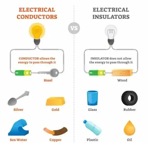
Insulator
An insulator is a material that does not allow the flow of electrons or has too much resistance to electron flow. This does not allow the current to flow. Insulator material includes paper, plastic, rubber, glass, air, etc. The material around the wires is an insulator that shields the wire conductor to prevent electric shock.
Conductor
The conductor is a material that does not resist or has the least amount of resistance to the flow of electrons. In conductors, the electrons can easily move from one atom to another atom when voltage is applied. Some best conductor materials are copper, silver, gold, aluminum, tungsten, and iron, steel. In-vehicle electrical systems, conductors are composed of solid metals molded into wires.
Battery Polarity
A Pole means a round rod of metal placed at the end of the battery plate. There are two types of poles in a car battery, positive and negative poles.
Polarity or electrical polarity is used to represent the electrical potential at the end of the battery. In batteries, one pole has more electrons than the other one. The pole with more electrons is said to have a negative polarity. The pole with fewer electrons then has a positive polarity.
When a circuit is closed, the two poles are connected by a wire, electrons flow from the negative pole toward the positive pole in one direction. This flow of electrons is called an electric current.
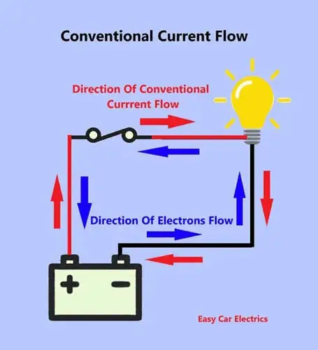
Now you may be wondering at this point by reading this twist that in a car battery, the electron flows from the negative pole to the positive pole, but remember, we assume that the electrons flow from the battery positive pole to the battery negative pole. This is called conventional current flow, where the battery’s positive polarity is considered a hot power source and the battery’s negative polarity is considered earth.
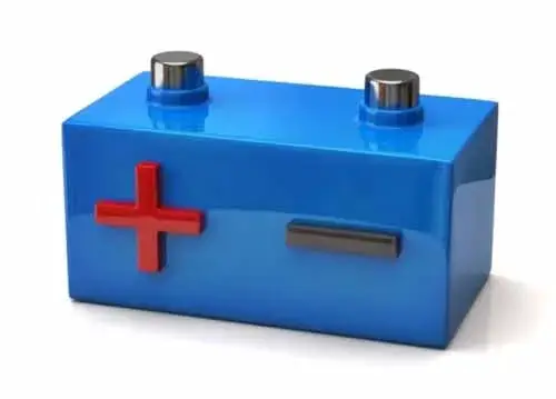
The battery positive pole is marked (+), which has a larger diameter post, and a negative pole is marked (-) and has a smaller diameter post.
In a modern car, the battery negative pole is connected to the chassis and engine, which is called the earth, and the positive pole provides live wire to components. But in older cars, the polarity was opposite where the battery positive pole was connected to the chassis and engine, and the negative pole was the live wire connected to the components.
This is an Info
Electrons flow from the negative pole to the positive pole, but remember, we assume that the electrons flow from the battery positive pole to the battery negative pole. This is called Conventional Current Flow.
Electrical Circuit
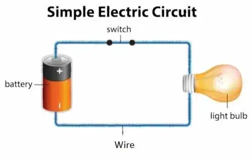
An electrical circuit is a closed route or path that allows the current to flow from the battery-positive pole to the battery-negative pole.
The current must have a closed loop to flow from the high potential to the low potential. You can consider it like a “Circular Closed Path” through which the electrons flow from the battery’s positive power source to the negative power source. If there is a break in the electrical wire, whether the switch is open or the fuse has blown, the current will not flow.
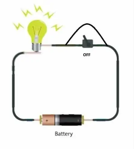
A fully functioning circuit contains a power source (battery), a load (Light Bulb), and wires. The switch is used to activate and deactivate the electrical circuit. One wire goes from the battery-positive power source to the load (Light Bulb). This wire is called a hot wire. The second wire goes from the load (Light Bulb) back to the battery-negative power source. This wire is called earth wire.
Here remember one interesting point, you can use the switch on any one of the wires (hot or earth wire) in the circuit. Some switches are installed on the hot wires such as windscreen wipers, but mostly in the vehicle, the switches are installed on earth wires like headlights, horns, etc. The same is true for the installation of the fuse. You can install the fuse on any one of the wires in a circuit. But it is better to install the fuse on the hot wire.
A simple form of the car electrical circuit is a headlight circuit, in which the current flows from the battery positive terminal to the component where it brightens the lamp, then the current returns back to the battery negative terminal through the earth wire.
This is an Info
You can use the switch on any one of the wires (hot or earth wire) in the circuit. The same is true for the installation of the fuse. You can install the fuse on any one of the wires in a circuit. But it is better to install the fuse on the hot wire.
Car Electrical System Diagram
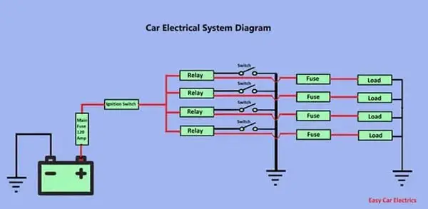
The car electrical system’s wiring diagram is not complicated, but the problem is, you will not find a basic diagram of a car electrical system on the internet. Here I have disclosed the basics of a car’s electrical system’s wiring diagram in easy words.
All the car’s electrical components are wired in the same way, if you have understood the basics; you will be able to diagnose any car’s electrical system problems easily.
So, let’s start.
The hot wire goes in the direction, from the battery-positive terminal to the fuse box to the ignition switch, and from the ignition switch back to the fuse box. There the hot wire goes from the fuse box’s relay to the fuse and then to the component and finally to the chassis where it returns to the battery negative terminal.
Didn’t get the point, let me explain.
Ideally, all the car’s electrical systems should have a fuse. The fuse is the basic element of the car’s electrical system. All cars have at least one main fuse almost 120 or 180 amp (depending upon the car manufacturer), which comes in the wireline from the battery to the fuse box.
From the fuse box, a hot power source cable having 80 or different amp fuse (depending upon the car manufacturer) goes directly from the fuse box to the ignition switch in the passenger compartment.
There the ignition switch controls and distributes the positive electrical source where needed to power the vehicle. The ignition switch wires especially, the ON and Accessory Positions wires go back to the fuse box. It is because; the component’s hot connections are directly taken from the fuse box, not from the ignition switch in the passenger cabin.
Here I am giving you a basic idea of the car’s electrical system wiring diagram.
That every component which needs the ignition switch ON or Accessory Position connections is taken from the fuse box’s ignition switch wires, not directly from the ignition switch in the passenger compartment. It is because of the reduction in the length of the wire. You do not need to install the wire for every component from the ignition switch to the fuse box.
The ignition switch’s high gauge wires connection is already present in the fuse box. You should understand, it is the basic thing.
Now here you should remember that when a component is wired, the hot wire (whether that is ignition switch ON or Accessory positions wires or a direct battery connection) is taken from the relay in the fuse box, which goes from the relay to the fuse and then to the component (load) where the load is connected to the chassis and the electrical circuit is completed.
It is the basic electrical wiring diagram, almost all cars use this method where the relay is the starting point, and then the wire goes to the fuse and then to the component (load). However, some car manufacturers start their electrical circuit from the fuse, then go to the relay and to the component.
Now I highly recommend, first you should read my article about relay so that you have a basic understanding of relay. After that, you will easily understand how the hot wire is taken from the relay in the fuse box to the component (load).
Here I will lightly touch the relay wiring diagram.
This is an Info
Every component which needs the ignition switch ON or Accessory Position connections is taken from the fuse box’s ignition switch wires, not directly from the ignition switch in the passenger compartment.
Related Post: Automotive Relay Diagram: 4 & 5 Pin Relay Wiring Diagram
A relay has two circuits, high and low amperage circuits. The low amperage circuit has two connections hot and earth connections. The hot connection of the relay’s low amperage circuit is taken from the ignition switch connection, present in the fuse box while the earth connection goes to the operating switch.
In the relay’s high amperage circuit one wire is taken from the battery hot connection, and the second connection goes to the component (load). You might be surprised by knowing this point that mostly the switch does not directly control the component whereas, the switch controls the relay, and the relay controls the component (load).
Let me elaborate on this point. You can take the example of the Windscreen washer pump.
This is an Info
Mostly, the switch does not directly control the component whereas, the switch controls the relay, and the relay controls the component (load).
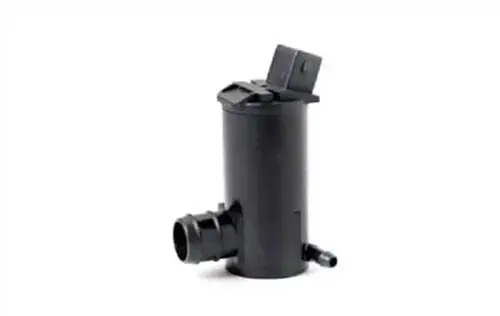
A windscreen washer pump runs when the ignition switch is, in the ON position. The washer pump relay takes the ignition switch current in the fuse box.

The washer pump relay’s low amperage (coil circuit) circuit’s one wire is taken from the ignition switch ON position connection present in the fuse box while the relay’s earth wire goes to the steering column switch.
In the windscreen washer pump relay’s second high amperage circuit, one wire is connected to the battery’s direct positive power source while the second wire goes to the washer pump. When you turn the key to the on position, it activates the steering wheel column switch, and the relay’s coil circuit is activated and starts to transfer the power to the washer pump.
Now, here I want to give you the insight that the switch is not connected directly to the windscreen washer pump whereas, the switch is directly connected to the relay.
The switch energizes and de-energizes the relay, and the relay energizes and de-energizes the component (load).
It means you operate the relay, and the relay operates the windscreen washer pump. You do not have a direct connection to the component (load).
Almost every component in the car is controlled by the relay and the relay is controlled by the related switch. It is the basic electrical system diagram.

You can take another example of the same wiring diagram about a horn or headlight.
The headlight or horn does not have a direct connection with switches, but they are controlled by the relays, and the relays are controlled by the switches.
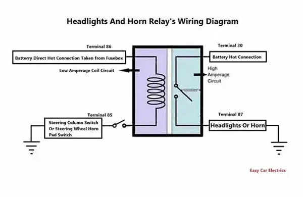
The headlight and horn are wired in the same manner. But the difference is the headlight or horn relay’s low amperage (coil circuit) circuit’s one wire is taken directly from the battery positive connection present in the fuse box.
While the relay’s earth wire goes to the steering column switch or steering wheel’s horn pad switch, and the remaining wiring diagram is the same.
The reason for taking the direct connection from the battery to the relay’s low amperage circuit is, the headlight and horn are not bound to the ignition switch, it can be operated even if the switch is, in the OFF position.
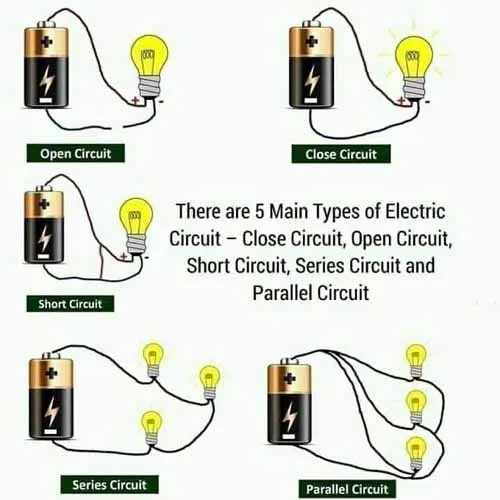
Types Of Electrical Circuit
There are five types of electrical circuits. Below is an explanation of the types of circuits.
- Parallel Circuit
- Series Circuit
- Open Circuit
- Closed Circuit
- Short Circuit
1. Parallel Circuit
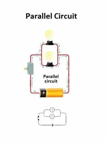
A parallel circuit is a type of circuit, in which the electrical components are connected parallel to each other between the same two points. In this circuit, the electric current has more than one path to flow through.
A parallel circuit has beauty, if one component fails, the other components will still function, as each component has its independent complete circuit. The car headlight is a good example of a parallel circuit in which both lights are connected in parallel.
If one headlight fails, then another headlight will still work. If these headlights were wired in a series circuit, then the failure of one headlight would break the entire circuit which will not let the other bulb work. In a parallel circuit, the total voltage across each component is the same, and the total current is the sum of the current flowing through each component.
This is an Info
A parallel circuit is a type of circuit, in which the electrical components are connected parallel to each other between the same two points. In a parallel circuit, the electric current has more than one path to flow through. This type of circuit is mostly used in a car’s electrical system.
2. Series Circuit
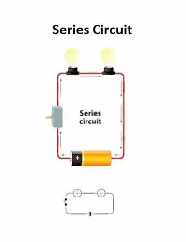
A series circuit is a type of electrical circuit, in which all the components are connected end-to-end one after another in a single line.
In a series circuit, all components are arranged in a row having only one electrical path for the current to flow in a circuit. The series circuit has one disadvantage if one component fails, the whole electrical circuit will burn out.
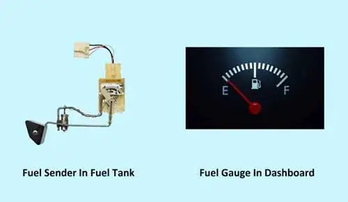
The car fuel sender in the fuel tank is an example of a series circuit, in which the fuel sender is wired in a series circuit. The fuel sender gives signals to the fuel gauge in the dashboard about the amount of fuel present in the tank.
When the fuel arm moves due to the increase and decrease of the fuel in the tank, it changes the resistance and sends a small electrical current to the fuel gauge which changes the needle in the fuel gauge on the dashboard.
The fuel gauge and fuel sender in the tank are wired in the series circuit. If one component fails the entire circuit will break, and the other components will not work properly. It is because there is only one path for the current to flow. Because of only one path for current to flow in a series circuit, the amount of current that passes through each component is the same.
3. Open Circuit
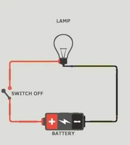
In automobile terminology, open means no flow of current in an electrical circuit. In an automobile, an open circuit refers to one where there is no continuity or a break for current flow in a circuit (which means an open circuit prevents the current from flowing into the circuit).
The current needs a complete closed path from the battery’s positive to a negative power source, including a load (component) in the middle of them. If there is a break anywhere in the circuit, the current stops flowing, it is called an open circuit.
The open circuit can occur due to many reasons such as an accident; a break in the wire, a loose or corroded connector loosely tied to two wires, or poor or burn-out connections. A corroded connector of an OFF headlamp is an example open circuit.
4. Closed Circuit
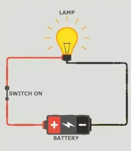
In an electrical circuit, a close means the current can flow in the circuit. The close circuit refers to the one where there is good continuity of current flow throughout the circuit.
A switch opens and closes the circuit under the control condition that connects the car’s light to the battery. An ON headlamp is an example of a closed circuit. The open and close also call out to the switch where the Open Switch means the OFF Switch (No Continuity) while the Close Switch means the ON Switch (Have Continuity).
5. Short Circuit
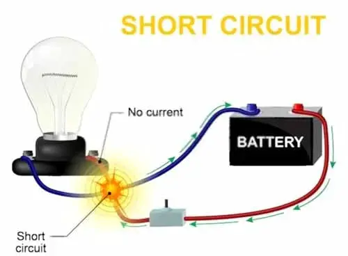
Generally, a short means a direct connection between two poles. It is a direct connection between the battery’s positive and negative power source without the current flowing through the component.
In a short circuit, the current travels through the least resistance path and does not pass through the component where it makes a direct connection between two poles. In other words, you can say, it is the least resistant connection between the battery’s positive and negative power source, which causes the elevation of current to a level where it can increase the temperature of the wire and can create fire.
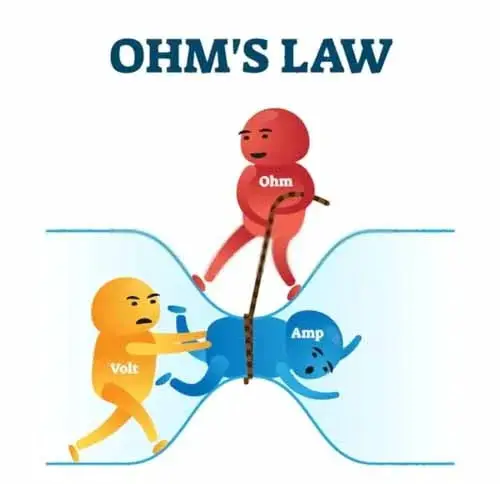
As the ohms law says,
Ohm´s Law I=V/R
It means zero resistance can cause infinite currents. The electron in a circuit has energy when the electrons flow from the battery’s positive terminal to the component; there the electrons lose their energy in the form of light illumination, and the energy-less electrons return to the battery’s negative terminal.
When a short circuit happens the electrons in the current bypass the component in the circuit and travels through a parallel path making a direct connection between the battery’s positive and negative power poles. In this way, all the full-of-energy electrons go directly from the battery’s positive to the negative pole, where it loses all the energy in the wiring making it overheat, which can spark and burn out the wiring.
A short circuit occurs when the insulation of a live cable breakdown. It can occur due to chafed, old age, overvoltage, heating effect, etc, and touches either the metal frame or another exposed earth wire. A short circuit can also occur due to wrongfully connected wires, which discharge the battery rapidly due to continuous current flow. To prevent the short circuit, the fuse is used to protect the circuit from overheating and melting.
Types Of Short Circuit
There are two types of short circuits, short-to-power, and short-to-ground,
A. Short-To-Ground
The term short is generally used for short to the ground means the battery live wire directly touches earth wire or metal frame bypassing the component in a circuit. In short to ground, the battery positive pole and negative pole have a direct connection, which prevents the pre-designed way of current flow.
For example, a breakdown of live cable insulation can short to ground. In this way, a large amount of current can flow directly from the positive to the negative pole causing too much heat in the circuit, which can burn out the circuit. A circuit having a fuse can blow in the event of a short-to-ground problem.
Related Post: How To Properly Ground A Car Battery: The Definitive Guide
B. Short-To-Power
A short to power is a short circuit of wiring in which the live wire is directly connected with the adjacent live wire. A shortage of power can also occur on the same live wire in which the same live wire creates a parallel path to the switch bypassing the switch. In such a way, the current still flows to the component even though the switch is open.
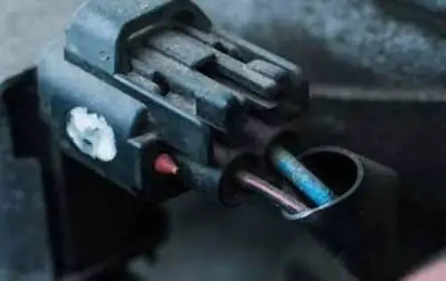
A headlight live wire running together in a wiring harness might be chafed due to rubbing and touches against other adjacent positive wires that may illuminate the headlight even though the switch is not closed. You can see this fault when you press the brake pedal, and the headlights turn on.
It is because the brake light live wire has touched the headlight’s positive wire somewhere in the line of the wiring harness. When the brake pedal is pressed the current goes from the live wire of the brake lights to the headlight’s positive wire and illuminates the headlight even though the headlight switch is OFF.
Car Electrical Wiring
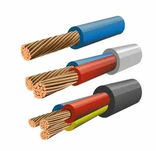
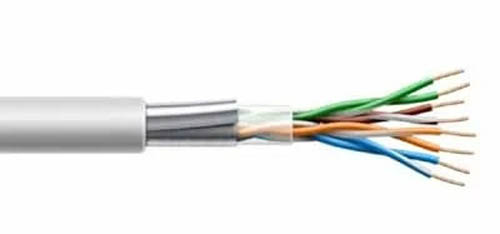
A wire is a flexible rod of metal of multiple strands of copper wire bunched together and encased in insulating PVC (Polyvinyl Chloride) material. Car electrical wire is used for carrying electrical power from the battery to the electrical components. It is also used for connecting the electrical components to the control modules.
The electrical current and control signals can be delivered to the electrical components through car electrical wires. The electrical wirings connect all the electrical components with sensors, actuators, and electronic control units. The higher the number of strands, the more current carrying capacity it has.
The car’s electrical wiring is the essential element of the car’s electrical system. The car manufacturers use the thinnest possible wire for an application while keeping minimum voltage drop in a circuit. The electrical wiring system must be reliable and safe so that the electrical system does not get impaired. You might be wondering by knowing that wire and cable are two different things.
The wire is a single electrical conductor and a component of cable whereas the Cable is a combination of multiple wires insulated together.
Related Post: Oxygen Sensor: 1, 2, 3, 4 Wire O2 Sensor Wiring Diagram
Wiring Harness
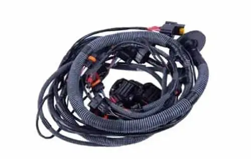
An organized set of wiring is called a Harness or Wiring Loom. The car has a massive number of wirings, which go side by side with each other. They are bonded together in plastic or fabric sheath to protect them from dirt and breakdown.
The wiring harness is routed in length and width of the car. Clamps are used to secure the wiring to the body of the car. Rubber grommets are utilized at the metal panel where the wiring harness passes for protecting the wiring against chafing and dirt.
Identification Of Wire
Wires in a car are identified by color for tracing the circuit while troubleshooting. Wires are color-coded by the car manufacturer to help the mechanic in finding the wire in the wiring harness in the auto repair operation. This wiring color code is used to avoid confusion while tracing the fault and repairing the car.
There is no universal rule for wire color coding. Every manufacturer has its own way of coloring the wire. It is different for every make and model. Even for one make, there are different color codes for different models.
Some car manufacturers use white color wire for carrying the current or for hot connection and black for ground. But that is not a universal rule. You should check the repair manual for color-coding while repairing. Sometimes, manufacturers use a few base colors and add a thin painted line in the base color to avoid using a high number of colors on the wires.
One Wire Circuit
Almost all cars are wired in the same way, once you understand the wiring circuit of one vehicle you will be able to understand and trace all the other cars’ wiring. In the past, vehicle manufacturers used more than a 1-kilometer wiring harness on the car and more than 2000 connectors, and relays, which would cause more than 30 kg weight on the car.
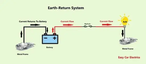
This increases the cost of the car and decreases fuel efficiency. That’s why car manufacturers use one-wire control circuits. Which, the current goes through a single feed cable from the battery-positive pole to the component and returns through the car’s metal body (Chassis) to the battery-negative pole by a thick cable.
This type of circuit is called the earth-return system or ground-return system. It saves costs and tons of wiring installation and also eliminates the need for additional wiring to complete the circuit. In the earth-return system, a heavy cable comes from the battery-positive power source to the ignition switch, where it distributes the electrical power to the components.
The electrical current first goes from the ignition switch to the fuse then to the component and returns via the metal body of the car to the battery negative terminal. Door wiring, tailgates wiring, roof wiring, headlights wiring, horn, etc are examples of wire circuits.
This is an Info
In an earth-return system or ground-return system, the current goes through a single feed cable from the battery-positive pole to the component and returns through the car’s metal body (Chassis) to the battery-negative pole by a thick cable.
Two-Wire Circuit
The two-wire circuit consists of two wires to complete the electrical circuit. One wire comes from the battery-positive power source, and the second wire completes the circuit and goes back to the battery-negative power source. This type of circuit is commonly used on the component, which is subject to frequent vibration.
Connectors
Electrical connectors are the connectors used to attach the cables to cables or electrical components. It is a necessary element in connecting various circuits and systems. A connector is used where it is desirable to disconnect the circuit when needed.
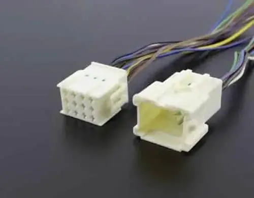
Electrical connectors have two parts, a male component (also called Plug) and a female component (also called a socket). The male component (plug) is designed to enter and fit into the housing called the female component (socket). Both components make a permanent or often a temporary connection that may be removable.
Connectors are designed to connect only when they are in the proper orientation. It has a locking mechanism that prevents the connector from accidentally opening. Electrical connectors are hundreds of types that are used according to specific electrical demands and applications.
Terminals

A terminal is the end of the wire used to provide conduction to make the connection secure. It is used separately or in connectors. Terminals have many types, such as ring terminals, spade terminals, push-on terminals, and pin terminals. All types have specific applications.
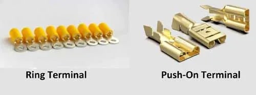
Such as a ring terminal that connects a wire to hardware like a stud or screw. A push-on terminal makes a quick connection between male and female terminals. The crimping tool is used to fit a terminal to the wire. The connection must be reliable and secure.
Unveiling the Costs of Car Electrical Repair – Find Out Auto Repair Cost
The cost to repair a car’s electrical issues will vary depending on the parts that need to be replaced and the number of hours that the repair team spends completing the job. The cost of auto electrical system repair will depend on the make and model of the car, as well as the complexity of the repair. Generally, the cost can range from $100 to $2000 and may be higher if a complete rewiring is needed.
It is recommended to replace the battery every three to five years as part of regular maintenance, that is the lifespan of the average car battery. A sign of a bad battery is when your car won’t start, makes clicking noises, or flickering lights, etc. These problems indicates a dead battery and needs to be replaced.
and car technician services are available to diagnose and repair car computer system issues. Diagnostics and transmission repairs may also be needed, and it’s important to select a reliable car electrical repair shop for these services.
The five main components of an automotive electrical system are the Fuse, Relay, Battery, Alternator, & Starter Motor.
The three main automotive electrical systems are the ignition, starting, and fuel systems. And a charging system is also very important system of the automotive electrical system.As a car owner, you should remember, it is important to keep these systems work together in a cycle to ensure a car’s electrical system running smoothly.
Loose connections, Overloaded circuits, and Electrical surges are the most common electrical problems causes. malfunction of the car causes various issues with your car and your vehicle may unable to start. It is better to fix these car issues as soon as possible to keep it running smoothly.
I will be very happy if you subscribe to my coming articles. Thanks for your precious time.
Sign Up


Adebayo, Thank you for your lovely comment. Soon I will write articles about cooling and lighting system.
AdeVic, Sure