
Whether you’re a professional electrician or a DIY enthusiast, understanding how to wire a relay is an essential skill. In this article, we will provide wiring diagrams of 4 pin and 5 pin automotive relays to help you better understand the wiring process. We’ll start with a brief overview of what relays are and why they are important for your electrical system.
Below is the complete guide about automotive relay diagrams such as four and five-pin relay wiring diagrams in easy-to-understand language.
What is A Relay And How Does it Work
Relays are important in vehicle applications because they can help prevent voltage drops, which can damage sensitive electronic components. An automobile relay is an electrical switch, which turns ON and OFF by giving an electrical trigger. It is made up of two circuits, a coil, and high amperage circuit. Each circuit has its pin numbers and wiring diagram.
It is a device that uses an electromagnet to open or close a circuit. When the current flowing through the coil of the coil conductor is increased, the magnetic field produced by the coil increases, which in turn attracts the armature and closes the contacts.
Related Post: Automotive Relay Guide: What It Is, How A 12V Relay Works & Components Of Relay Switch
12v Automotive Relay Wiring Diagram
The automotive relay wiring diagram is not complicated, it’s very easy. All you need to know is the basics of a car relay wiring schematic.
Here in this section, I am explaining the 12 volt electrical diagram of the four and five-pin car relays. Stick with me, here I am giving you a little background about automobile relay connection points.
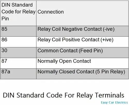
In the last century, Germany made an organization called DIN Standard. It stands for Deutsches Institut für Normung means the German Institute for Standardization. This national organization gives standard numbers (Known as DIN Standard) to almost every field of technology, covering almost thirty thousand DIN Numbers. The DIN organization also gives a standard DIN code to motor vehicles.
The standard code for electrical connection points is known as DIN 72552 standard and is almost accepted throughout the world. DIN standardizes almost every connection point in an automobile with code. Here we will only discuss the relay’s connection points. Below is the circuit diagram of the four and five-pin car relays.
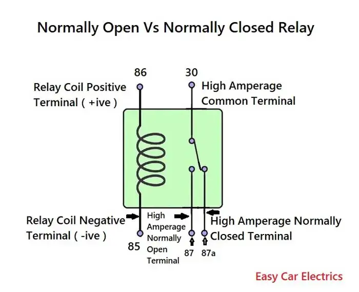
According to DIN 72552 Standard, each pin of a relay is numbered 85, 86, 30, 87, and 87a.
You need to know that a relay has two circuits, a coil circuit (also called a “low current circuit”, or “inductive circuit”), and a high-amperage circuit. In a relay 85 and 86 pins are considered coil circuit pins while 30, 87, and 87(a) pins are considered high-amperage circuits.
Coil Circuit Pin Numbers
-85 and +86 are called coil terminals. Usually, one terminal -85 is given a ground power source, and connection point +86 is given a hot energy source, to make a complete circuit. A diode is used across the inductive circuits (coil-circuit) in a relay to avoid high voltage spikes.
High Ampere Circuit Pin Numbers
Terminal 30 is considered to be a common connection point. 12-volt power comes to a relay through this connection point (we can say Power-In Wire).
And the second wire of high amperage or current circuit terminal 87 gets power out of the relay and sends it to the component (we can say Power out Wire).
There is also a third wire that comes in the high current circuit of a 5-pin relay, which is called terminal 87a. It is the extra fifth terminal, which is not commonly used in automobile relays. It is used for circuits that need power when the relay is not activated.
Related Post: Types Of 12V Automotive Relays – 3, 4, & 5 Pin Relays
4 Pin Relay Wiring Diagram
Car Relay Diagram
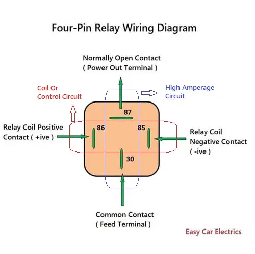
In the above four-pin relay schematic, there are four connection points, two connection points for inductive circuits, and two for high-amperage circuits. The inductive circuit’s two connection points are 85 and 86, in which connection point 85 is the relay’s coil negative contact, and terminal 86 is the relay’s coil positive contact.
Similarly, the high amperage circuit’s two connection points are 30 & 87 in which connection point 30 is a common contact, which means it is an input contact, through this connection point the current goes into the relay whether that is positive or negative depends on the demand of energy source.
And connection point 87 of the relay is normally open contact and closes when the relay is powered up. It is also called an output connection point, which means the currents go out of the relay through this connection point to the component.
5 Pin Relay Wiring Diagram
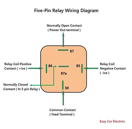
In a five-pin relay, there are five terminals, two connection points are for the inductive circuit, and three connection points are for the high-amperage circuit. The inductive circuit’s two wires are terminals 85 & 86, in which terminal 85 is considered a negative terminal and connection point 86 are considered a positive terminal.
The five-pin relay’s high current circuit consists of three connection points 30, 87, and 87a. connection point 30 is a common contact, the battery power comes through this connection point to the battery. connection point 87 is an open contact and always stays open, and closes when the relay is powered up. The power goes out through this connection point to the component when the relay is powered up.
Similarly, connection point 87a is a normally closed contact, and its contacts open when the relay is powered up. It means, by default, it lets the current out without energizing the relay and stops the current when the relay is powered up. It is used in applications where the current is required when the relay is not powered up.
4 Pin Relay Wiring Diagram For Lights
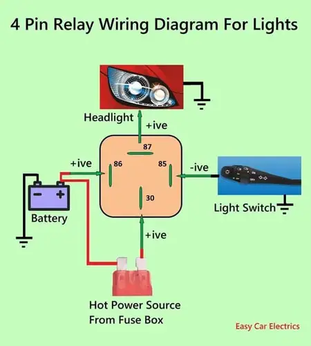
The above is the circuit diagram for the lights. connection point 86 wire of the “inductive circuit” (coil circuit) is connected to a hot energy source, while connection point 85 is connected to a light switch, which is often a ground energy source.
A fused wire comes from the fuse box to connection point 30 of the high-amperage circuit, while the second terminal 87 is connected to the headlight. The coil circuit consumes almost 0.5 amp current, which is a not burden on the light switch, as a result, will not burn the light switch.
So, when the inductive circuit is activated, the high-amperage circuit will make the contact, and the current will directly flow from the fuse box’s battery connection to the lights and the light bulb will illuminate.
4 Pin Relay Wiring Diagram For Horn
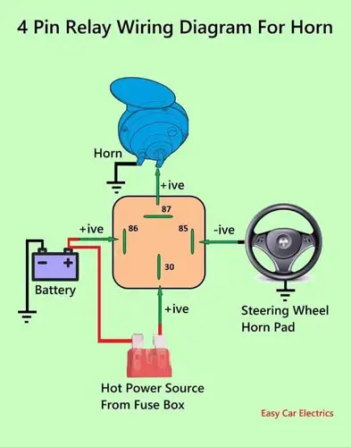
The above is the 4 pin relay wiring diagram horn. The relay inductive circuit’s connection point 86 is connected to the battery’s positive energy source, while negative connection point 85 is connected to the steering wheel horn pad, which is a ground energy source.
And connection point 30 of the high-amperage circuit of the horn relay is connected with fused wire from the fuse box, while connection point 87 of the high-amperage circuit is connected to the horn.
Note:
Whichever energy source (positive or negative voltage) you give to the common connection point of the high-amperage circuit of terminal 30. It will output that power to connection point 87 or 87a of a load wire.
For example, if you give a connection point of 30 hot energy sources. In a de-energized state, the relay will power a hot energy source to the 87(a) connection point while in an energizing state, it will output a hot energy source to connection point 87.
The same goes for ground energy sources too.
A Good Way To Remember Relay Wiring Diagram
Some people have difficulties identifying pin numbers and connection points. I use a technique that helps me remember the pin connection points.
Usually, relay pin numbers are 30, 85, 86, and 87 (In four-Pin Relay). Here, just for a while put connection point 30 aside then the remaining connection point will be 85, 86, and 87. Now at this time assume that 85 & 86 are starting numbers in the above connection points and also take the inductive circuit of the relay as the initial circuit.
Now link in mind starting numbers represent the initial circuit. It means that connection points 85 & 86 represent the inductive circuit. So, whenever you hear about the inductive circuit remind yourself that It means connection point 85 & 86.
In this way, you can easily remember inductive circuit pin numbers. Finally, the remaining two connection points 30 & 87 are for high-amperage electrical circuits. In which 30 connection point represents a common wire and 87 connection point is power out or load wire.
Related • How To Wire A 4 Pin Relay For Horn & Lights With Diagram: No More Confusion
FAQs
Using a relay is an effective and efficient way of controlling electrical circuits on low voltage without having to use direct current. A four-pin relay is typically wired with 2 pins (85 & 86) connected to a coil conductor, one for power and the other to the ground. The other two pins (30 & 87) switch power on a single circuit. There are two types of four-pin relays available, normally open pin and normally closed pin. If you want a normally closed relay, you will want to wire to 87(a). If you want a normally open relay, you will wire to 87.
A 12v relay typically has four terminals, labeled 85, 86, 30, and 87. connection point 85 is for the control voltage (negative contact) and connection point 86 is for the control voltage (positive contact) return. connection point 30 is for the main power supply (common contact) and connection point 87 is the main power (normally open contact) return. Depending on the type of relay, additional connection points may be available for specialized applications.
Pins 30 & 87 are contact pins that are used to power switching between dual circuits. When the relay is at rest, pin 87 is normally open and pin 87(a) is normally closed. When the coil is powered up using pins 85 & 86, pin 30 connects to pin 87(a), completing the circuit.
The positive pin in a relay is commonly referred to as pin 86. This pin serves as an integral component of the device’s electrical system, This pin is responsible for connecting the normally open and normally closed pins. More specifically, its purpose is to complete the circuit between the control system and the load, thus enabling the initiation of switching operations.
Pin 30 on a relay can be understood as the power supply pin, which is usually connected to battery voltage or other DC voltage sources. This pin provides the necessary operational voltage. It should be noted that while pin 30 may not be utilized in all relays, it is typically found in a standard single pole single throw (SPST) and single pole double throw (SPDT) relays used in many applications.
87(a) on a relay is a designation for the normally closed contact, which is one of two types of contacts found in relays. This contact allows current to flow when the relay coil is de-energized and it opens when the relay coil is powered up. It acts as a switch, allowing electricity to flow from one point to another when the circuit is in its off state.
The difference between 4 or 5 pin relays is as follows. 4-pin relays are used to control a single circuit, while 5-pin relays switch power between dual circuits. The 4-pin relay acts as a high-power ON/OFF switch, while the 5-pin relay includes an additional ’87a’ or Normally Closed (NC) pin. The connection points on the outside of both the 4 and 5-pin mini relays provide a good electrical connection, however, the fans may not start with ‘key on’ if the relay does not follow the DIN ‘norm’ for pin-out.
Sign Up


THANK YOU, Mr. Khan. Finally, I have found a clear and complete explanation of the Relay and its uses. I am rewiring an old Oliver 55 farm tractor and its ignition system uses 12v power and is grounded Positive which further confuses my very limited knowledge of the fascinating field of electricity. I stayed out of these matters most of my life because I suppose as a child I was told it is very dangerous, so leave it alone. U-Tube has been some help, but the explanations are rarely complete. For me to learn (slowly) I have to understand “why it works” as much as “how”.
Greg Davies, My pleasure