
A relay is an electrical switch used to control a high amount of current by using a little amount of current. The vehicle wirings are of a normal gauge that can not carry a huge amount of current. It needs a relay to manage a high amount of current by consuming less amount of current so that the wirings get protected from damage.
If you really want to master the skill of wiring a car relay by yourself, this page is for you. I will show you how to wire a 4 pin relay for the horn and driving lights. On this page, you are going to quickly learn the skill of wiring a car relay by yourself without an expert with a practical demonstration of wiring the four-pin car relay for horns and lights.
Related Post: Car Relay Guide
Start Your Journey Into Relay Basics!
Installing a relay is not a hard task provided that you know the schematics of the relay. Before installing the relay, you should understand the wiring diagram of the relay. First, we will explain the four and five-pin relay wiring diagram so that you have a good understanding of the relay diagram. After that, you can easily wire a relay.
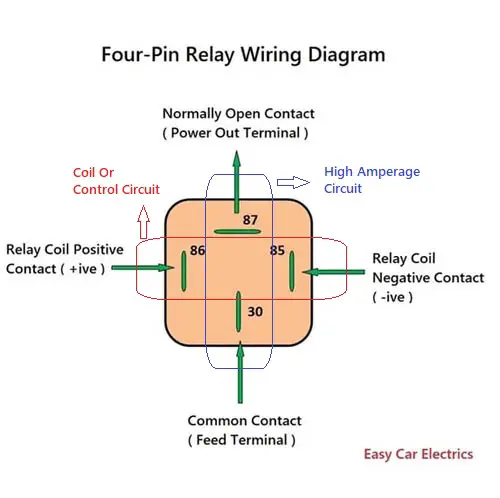
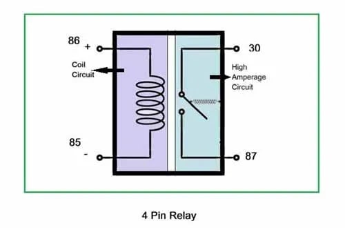
A relay has four basic terminals, 85, 86, 30, and 87. A five-pin relay has an extra fifth terminal called the 87a terminal. A car relay has two circuits, a coil circuit, and high amperage circuit.
The coil circuit has two terminals called 85 and 86 terminals, in which terminal 85 is considered a negative terminal and is given a ground power source while 86 is considered a positive terminal and is given a hot power source. The coil circuit is the circuit when you give it the power, you hear a clicking sound. So, whenever you connect the battery power source to the two wires of the relay and it produces a clicking sound, then understand it is the coil circuit.
Similarly, a relay’s high amperage circuit has two terminals called 30 and 87, in which terminal 30 is considered a common terminal means the battery’s 12-volt power comes through this wire to the relay. While terminal 87 is a power out terminal, which means the 12-volt power exits from the relay to the component.
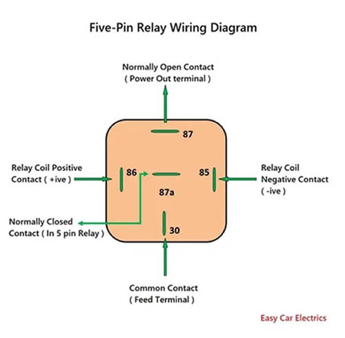
There is also a fifth terminal 87a which comes in the five-pin relay. This terminal is needed when power is required without energizing the relay, and by energizing the relay, the power is cut off. As you have understood the wiring diagram of the four and five-pin relay, now here is how to wire the relay.
How To Wire A 4 Pin Relay
Wiring the relay is very easy, it’s not a complicated thing. You can wire a relay by yourself without getting confused. When you learn the skill of how to wire a 12-volt relay in the car, you can easily connect any kind of four-pin relay into a circuit.
Related Post: Purpose Of a Relay in a Car
Step 1. Get Prepared
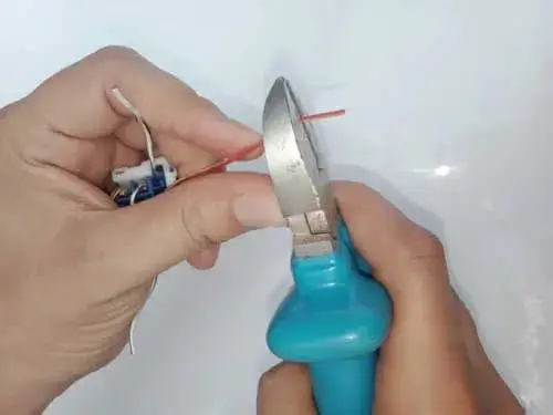
- Strip for one inch of the insulation from the end of all wires of the relay.
- Figure out the coil and high-amperage circuit terminals.
- Check out the relay wiring diagram for correct wiring.
This is an Info
You can identify the coil circuit by attaching one after two wires together with battery positive and negative poles, you might hear a clicking sound when the relay’s coil circuit (Terminal 85 and 86) activates. And the other two wires are for the relay’s high amperage circuit.
Step 2. Make Connections
- In the coil circuit’s terminals 85 and 86, connect one terminal of the coil circuit to the switch and connect the other terminal with the battery.
This is an Info
Connecting the relay’s coil circuit terminals with battery poles depend on the switch power source, if the switch has a ground power source, the relay’s second terminal must be connected with a battery hot power source and vice versa
- Now connect terminal 30 of the relay’s high amperage circuit to the power source.
This is an Info
Connecting the relay’s high amperage circuit terminals 30 with battery poles depends on the load component, if a component needs a hot power source then connect with a battery hot power source, and vice versa
- And connect the second terminal 87 of the high amperage circuit to the component.
Related Post: Normally Open Vs Normally Closed Relay
Step 3. Tape Into The Wires
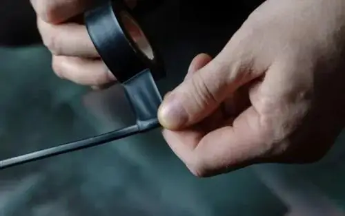
And done.
You have successfully wired the relay. Now, tape carefully the exposed joints. That’s all it is. In this way, you can wire a 12-volt relay to the circuit.
How To Wire 4 Pin Relay For Lights And Horn
As you have learned the art of wiring a relay, now, here is the practical demonstration of wiring the four-pin relay for light and horn.
- How To Wire 4 Pin Relay For Lights
- How To Wire 4 Pin Relay For Horn
Related Post: SPST Relay Vs SPDT Relay
How To Wire A Relay For Lights
4 Pin Relay Wiring Diagram For Lights
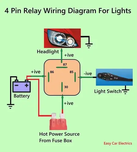
Below is the step-by-step procedure for wiring the four-pin relay for lights.
Step 1. Connect The Relay’s Coil Circuit
- Connect the coil circuit’s terminal 86 to the battery-positive power source.
- Connect the coil circuit’s terminal 85 to the light switch.
Step 2. Connect The Relay’s High Amperage Circuit
- Similarly, connect a fused wire which comes from the fuse box to the high amperage circuit’s terminal 30 of the relay.
- Connect terminal 87 of the high amperage circuit to the headlight.
And you have finished wiring the four-pin relay for light.
How The Four-Pin Relay Works For Headlights
You can see, the battery-positive power source is connected all the time with the relay terminal 86. Whenever the driver turns ON the light switch of terminal 85, the relay’s coil circuit is energized, which allows a high current to flow from terminal 30 of the fused wire from the fusebox to the headlights. Hence, the headlights illuminate.
How To Wire 4 Pin Relay For Horn
12v 4 Pin Relay Wiring Diagram Horn
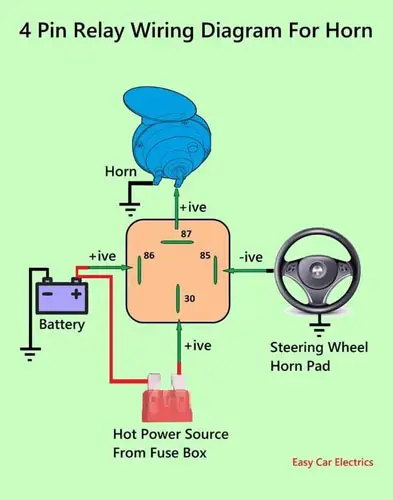
It is also a dual horn relay wiring diagram. You can connect two horns with terminal 87 of the relay. Below is the step-by-step procedure for wiring the four-pin relay for the horn.
Related Post: Types Of 12V Automotive Relays
Step 1. Connect The Relay’s Coil Circuit
- Connect the coil circuit’s terminal 86 to the battery-positive power source.
- Connect the relay’s coil circuit’s terminal 85 to the steering wheel horn pad.
Step 2. Connect The High Amperage Circuit Of the Relay
- Similarly, connect a fused wire which comes from the fuse box to the high amperage circuit’s terminal 30 of the relay.
- Connect terminal 87 of the high amperage circuit to the Horn
- And Done. You have successfully wired the four-pin relay to the horn.
How The Four-Pin Relay Works For Horn
The horn relay starts working by pressing the steering wheel horn pad. The battery-positive power source is connected all the time with the relay terminal 86 of the coil circuit.
Whenever someone presses the steering wheel horn pad of terminal 85, the relay’s coil circuit is energized. This coil circuit allows the current to flow from terminal 30 of the fused wire from the fusebox to the car horn. In this way, the horn’s relays are wired in the car.
I will be very happy if you subscribe to my newsletter and share it with friends.
Sign Up


Thanks for putting this up. I’ve got an air horn from Harbor freight and it just quit. I replaced the relay and have in line fuse in it. But still don’t work, what could the problem be? Do you have any idea?
Thanks for your time. JAMES L.
Hi JAMES, Thanks for your comment. Look for the horn, its connector, loose wiring, and the relay order.