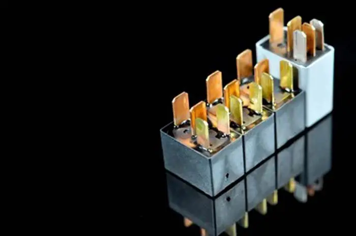
Automotive relay is an electromagnetic switch that is used to control a circuit through a low-voltage signal. This kind of relay is often used in automobile applications, such as headlights, horns, and starter circuits. The relay allows the control circuit to be isolated from the load circuit, which can be useful in preventing electrical shorts and protecting the control circuit from high currents.
There are many different types of automobile relays, each with its own specific purpose. If you want to know more about types of automobile relays, read on. You’ll learn about the different types of automobile relays and how they work.
12V Automotive Relays
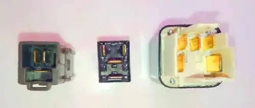
12v automotive relay is a broad subject in the automotive industry for vehicle electrical systems. It comes in many different types, designs, and sizes. Each relay has its application.
Some types of relays are Electro-thermal Relays, Solid State Relays, Hybrid Relays, Reed Relay, and Electro-mechanical (Electromagnetic) Relay. Here our focus will be on the electro-mechanical type relay because it is widely used in automobile applications.
Electro-Mechanical (Electromagnetic) Relay
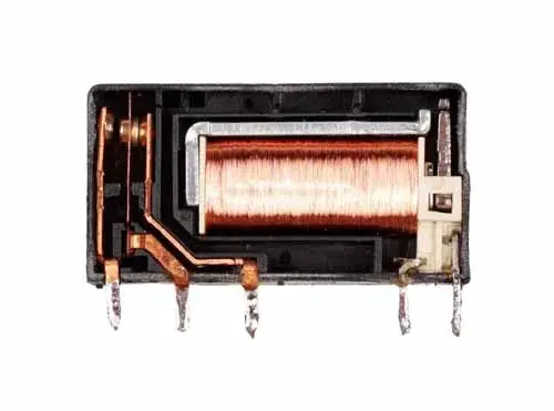
One of the relay’s functions is to perform logic functions. Relays are used for momentary input, time base function, and doing alternative work (like flushing alternative left or right lights) according to the built circuit board inside the relay.
Some examples of logic functions in a car are interior lights and the time delay operation of wiper blades. Since a mechanical contact (A movable contact that makes & breaks the connection) and an electrical coil (which produces a magnetic field when current flow through the coil to attract movable contact) is used to join a set of contacts that is why a car relay is called in, either way, Electromechanical or electromagnetic Relay.
An electromechanical relay comes in many shapes and sizes. All are used for various demands of various applications. Here are some most common types of electromechanical relays.
1. Timer Relay
A Timer relay is operated for a while before turning off. A good example is the heated rear window, where the relay is activated for a while and then is turned off.
2. Fuel Injection Relay
A Fuel injection relay electronically operates fuel injectors in the petrol engine.
3. Flasher Relay
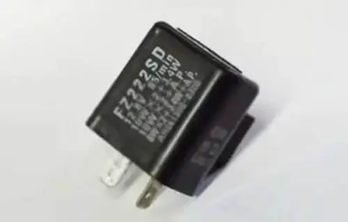
Flasher relays are thermally controlled. The current generates a heat flow within the coil of the flasher relay. which causes contacts inside the relay to deflect, causing the contacts to open and stopping the current flow. Almost all cars have a flasher relay. They are used for indicators and hazard warning lights.
4) Glow Plug Relay
The Diesel engine uses a relay to heat the glow plug for some time.
Related Post: What Is The Purpose Of A Relay In A Car: The Ultimate Guide
Types Of Automotive Relays
Relays come in different voltage ratings 5, 6, 12, and 24 volts. It also comes in different sizes and designs.
5 volts relays are found especially for automotive sensors. These kinds of relays are also very common in the car.
Electromagnetic relays are a traditional kind of relays used in an automotive vehicle. Most of the relays are 12-volt and some cars have a high voltage of about 24-volt. Here are the most common types of relays used in cars.
- 4 Pin Relay (Make And Break Relay)
- 5 Pin Relay (Changeover Relay)
- 3 Pin Relay
4 Pin Relay (Make And Break Relay)
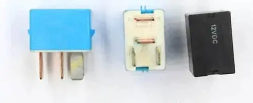
Four-pin relays are the most common type of car relays. It is the most widely used in many types of vehicles.
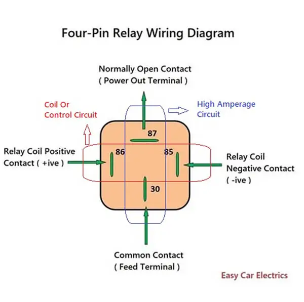
Most automotive relays you see in a car are 4-pin. In a four-pin relay, there are two circuits, primary and secondary circuits. Each circuit/path has two cables.
Sounds good, doesn’t it? Let me further elaborate.
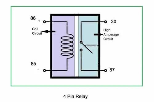
The primary circuit/path is also called a coil circuit consisting of terminals 85 and 86. Similarly, the secondary path is called high amperage or load circuit consisting of terminal pin 30 and pin 87. In the coil circuit terminal, 85 is usually connected to a negative power, and the remaining terminal is connected to a positive power source.
But be cautious, here is the risky point. If you connect it the other way, you are more likely to harm the device, especially when it is connected to a sensor or transistor. It is because, the coil circuit/path produces a voltage spike when the current is removed, which can harm the electronic devices. Therefore a diode is fitted across the coil current path to dump the electrical spikes when the relay is opening or closing.
In the secondary circuit/path, one cable which goes to the relay is called terminal 30. It is also called “The Power In” terminal, and the second terminal is 87, also called the load terminal or power out terminal. It means when the relay is activated, the power goes in through terminal 30 and exits through terminal 87.
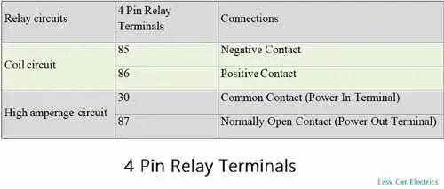
Whenever a relay is energized, the secondary current path’s common cable contact comes closer to make a connection with the load cable (30 and 87 Terminal).
On the other hand, when the relay is de-energized, the secondary current path breaks and disconnects the current passage. That is why a four-pin relay is also called a “Make and Break Relay”. Usually, a car horn system uses a 4-pin relay.
Related Post: How To Wire A 4 Pin Relay For Horn & Lights With Diagram
5 Pin Relay (Changeover Relay)
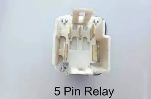
A five-pin relay is a type of car relay, which has five pins. It is mainly used for current paths that need power when the relay is at rest.
In other words, a five-pin relay is mainly used for current paths that are normally open instead of normally closed. It comes in various designs and pin arrangements but, the main function is the same.
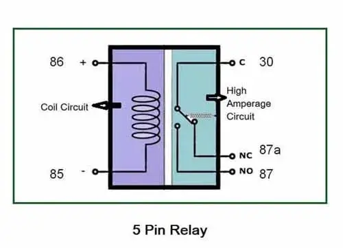
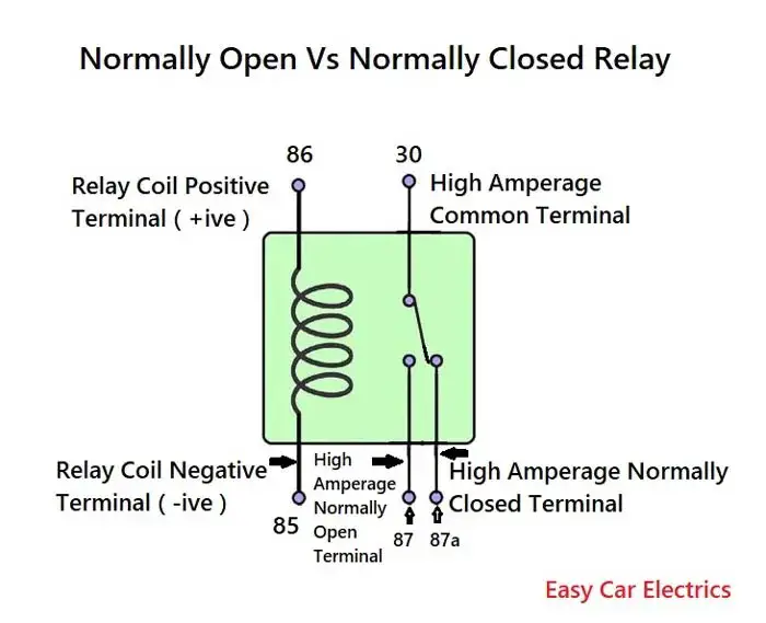
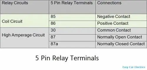
By energizing and de-energizing the relay, the movable contact of the high current circuit shifts back and forth to 87 and 87a terminals. Due to these changing features, the five-pin relay is also called Changeover Relay.
When there is no voltage applied to the coil current path, one current path of high amperage (terminal 30 to 87a terminal) is in touch with each other and can receive current, but the other terminal (terminals 30 and 87) does not receive current. When the coil current path gets energized, the relay switches current from one circuit to another and the secondary current path of high amperage (Terminals 30 and 87) starts to receive current.
A five-pin relay is usually used in headlight current drawn operation where the relay can switch between two contacts of current paths to activate the high beam and low beam as required.
Related Post: 4 Pin Relay Wiring Diagram & 5 Pin Relay Wiring Diagram
3 Pin Relay
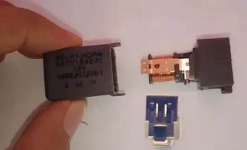
Here, I explain the three-pin relay in the last, because when you have a better understanding of the four and five-pin relay, then it gets easy for you to understand a three-pin relay.
A three-pin relay is a type of car relay, which has three pins. It works on the same principle as a four and five-pin relay. Its basic construction and operations are the same as those of four and five-pin relays.
In a four-pin relay, four wires/cables come out of the relay. Two wires/cables are for the coil current path (using pins 85 and 86) and the remaining two are for the high amperage current path (using pins 30 and 87). But, here is a twist.
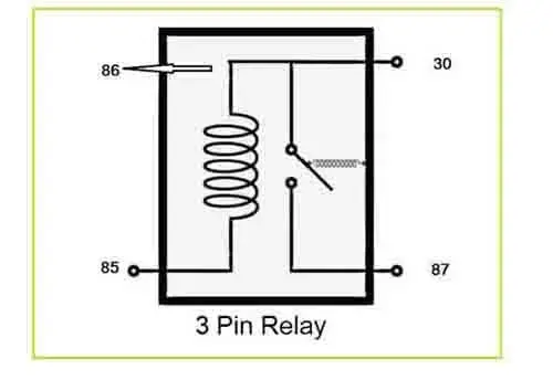
In the three-pin or three-prong relay coil circuit, the 86 terminals (which are usually connected to a positive power source) are connected internally to the high amperage circuit of terminal 30. Both wires (Terminals 86 and 30) are joined together and come out as a single wire from the relay.
And other two wires (85 terminal of coil current path and 87 terminal of high amperage current path) also come out separately.
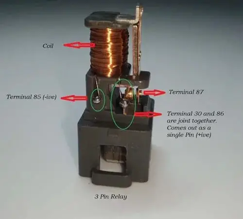
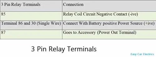
Here you should remember one thing. Always connect the hot power source to the joint terminal (Terminals 86 and 30). And the other two terminals, terminal 85 should be given to the low current circuit which is ground, and 87 will be the go-to accessory. So, the total numbers of pins are three “85, 30, and 87”.
These relays were used in older cars, especially for horns. Nowadays these three-pin relays rarely come in a car for horns.
Related Post: How To Test A Relay With A Battery (With Pics): The Easy Way
How to Find Automotive Relay Diagrams For Specific Vehicles
There are a few ways to find automotive relay images for specific vehicles:
- Consult The Vehicle’s Owner’s Manual: Many vehicles come with a manual that includes information on the car’s electrical system, including relay images.
- Search Online Using The Make, Model, and Year Of The Vehicle: There are many websites that specialize in providing repair and maintenance information for specific vehicles, and these may include relay images.
- Visit A Dealership Or Repair Shop: Dealerships and repair shops often have access to relay images for specific vehicles, and they may be able to provide you with a copy.
- Check For Aftermarket Repair Manuals: There are many aftermarket repair manuals available for purchase that provide detailed information on specific makes and models of vehicles, including relay images.
- Search For The Vehicle’s Wiring Image: relay pictures are often included in a vehicle’s wiring image. Most relays have circuit diagrams printed on the side of the relay.
- Try To Contact The Manufacturer: Reach out to the manufacturer of the vehicle and ask if they can provide you with a relay picture.
It’s important to note that not all vehicles have relay pictures readily available and it may take some effort and research to find the right one.
Conclusion
Automotive relays allow control circuits to be isolated from load circuits, which is useful in preventing electrical shorts and protecting control circuits from high currents. There are various types of automotive relays, including Electro-Mechanical or Electromagnetic-Relay, Timer-Relay, Fuel Injection-Relay, Flasher-Relay, and Glow Plug-Relay, with different shapes, sizes, and applications. The most common types of relays used in cars are 3-Pin, 4-Pin, and 5-Pin Relays.
FAQs
A mini relay is a small electromechanical switch that can be used to switch current from one current path to another and back. It is different from other types of relays because of its small size and typically has fewer pins than larger relays.
When a relay is at rest, its contacts are either energized or de-energized, depending on its configuration. When the relay is activated, the contacts inside the relay deflect, causing the switch to either open or close, completing a circuit or interrupting one.
Relays are common in various configurations such as single pole single throw (SPST), single pole double throw (SPDT), and four and five-pin configurations. Each configuration has a unique way of handling the current required and switching it between current paths.
A flasher relay is a kind of relay that is used to alternate between two separate lamp circuits. These relays are thermally controlled like a circuit breaker, meaning that they use a resistor or an integrated circuit to regulate the amount of current passing through the relay, which helps to prevent overheating.
ISO mini relays are a specific automotive relay type that conforms to a set of standardized specifications. They typically have electrical terminals that are arranged in a specific way, and they are used in a variety of different automotive applications. The German automotive industry has been instrumental in developing these relays, and they continue to be widely used in automobile applications around the world.
A micro relay is a compact and lightweight kind of relay commonly used in automotive circuits. It is similar to a normally open relay in that it allows current to flow through the circuit when activated, but it is designed to handle lower current loads.
Indicator lights and fuses are important components to include in a relay schematic. The indicator light is used to show whether the relay is activated, which can help identify any issues quickly.
Sign Up


