The starter motor is a critical component of a car’s electrical system and is responsible for starting the engine. A starter consists of a powerful DC electric motor that is used to turn the engine over and start the car. It is turned by a key or a button, which activates a solenoid that turns the starter motor. The starter motor is powered by a battery and turns the engine over until it starts.
It works by converting electrical energy into mechanical energy, which then turns over the engine. The starter motor is typically located at the front of the engine and is connected to the battery. When the starter button is pressed, a small amount of current from the battery flows through the starter solenoid, which energizes the starter motor. This article will provide a diagram of a typical starter motor, as well as an explanation of it.
What is A Starter Motor
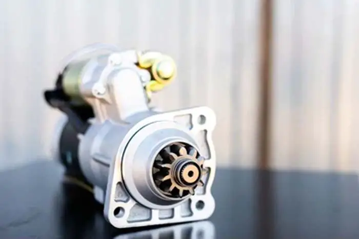
Before we delve into the start motor schematic, we will first spend a moment talking about what a starter motor is. A starter motor is an electronic device that’s used to crank an internal-combustion engine by providing an initial push. It is usually located in the engine’s flywheel housing to begin the engine. When you turn the key in your car’s ignition, it sends an electrical signal to initiate the starter motor. From this signal, the solenoid throws the starter gear forward to mesh with the engine flywheel ring gear to start the first combustion cycle. As soon as the engine starts running, the starter system disengages from the engine.
What is a Starter Motor Diagram
A starter motor diagram is a visual representation of a car’s starter motor assembly, outlining various parts of starting system including the starter wiring, and starter control circuit. It is a useful tool for understanding how the starter motor works, identifying issues, and carrying out repairs.
Parts of a Starter Motor
A starter motor schematic comprises several parts inside the starter motor, each with its unique function. Here are the primary parts of a starter motor.
- Armature: The armature is an electromagnet component that consists of a set of windings and a commutator. It is available to convert electrical energy from the battery into mechanical energy to spin the engine crankshaft. A lever fork attached to the plunger inside the solenoid connects the starter motor with the solenoid.
- Commutator: The commutator is a segmented cylindrical component that makes the connection with the armature shaft. It serves to reverse the direction of the electrical current passing through the armature windings, ensuring that the armature rotates in a single direction.
- Brushes: The brushes are spring-loaded carbon blocks that attach to the commutator, allowing the direct current to flow through the armature windings.
- Field coils: The field coils are a set of wire windings wrapped around a magnetic core. They generate a magnetic field that interacts with the armature’s windings, causing it to spin.
- Pinion Gear: The pinion gear is the small gear located at the front end of the armature shaft followed by an overrunning clutch. It is used to transmit torque from the motor to the flywheel for rotating the engine.
Starter Motor Diagram
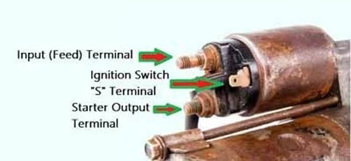
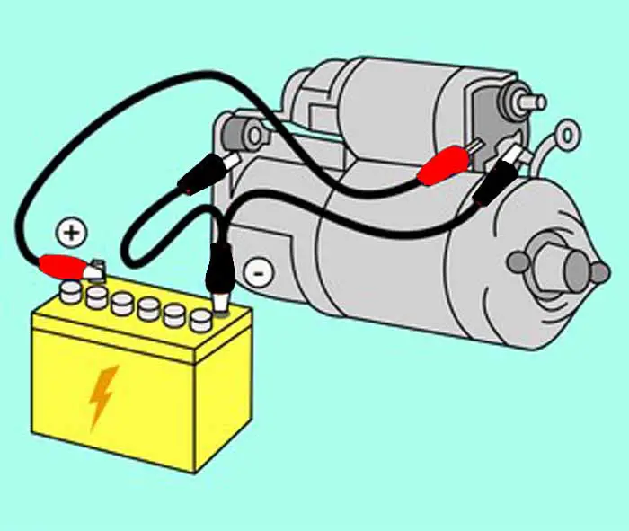
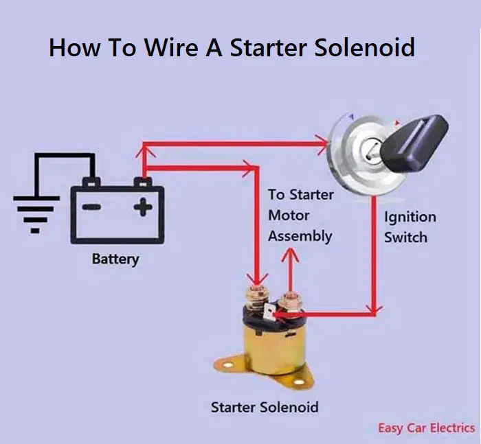
A starter solenoid has three terminals, one small pin-type, and two thicker bolt-type terminals. The small pin-shaped terminal is called the “S” terminal. The “S” terminal links with the ignition switch circuit. The starter solenoid has one thicker terminal as the input one, where the battery positive power source enters the solenoid, and the second thicker one is the output terminal, which goes straight to the starter motor assembly.
Related Post: 6 Complete Starter Solenoid Parts, Functions & Working

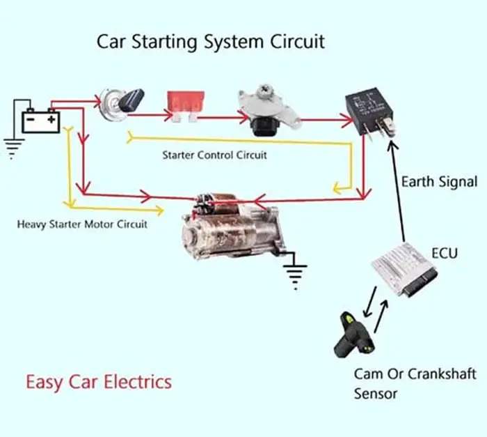
Remember, the starting motor uses two wiring circuits to complete its operation. The first one is the control circuit, and the second one is a heavy electric circuit. The control circuit turns ON and OFF the solenoid and is controlled by the ignition switch. It consumes less current, and these cables are thin compared to the second circuit.

The control circuit starts from the start switch and goes to the starter fuse then to the neutral safety or clutch pedal safety switch to the starter relay in the fusebox and finally to the starter solenoid “S” terminal. The second circuit is a heavy-current-drawn one. This circuit goes directly from the battery through a heavy cable to the solenoid and then to the starter motor assembly. When activated, the starter motor armature turns.
When the driver turns the key to the start position or presses the start button in the keyless car, the current flows from the ignition switch or ECU to the starter fuse to relay in the fuse box. This fuse box starter relay provides a bigger current to the solenoid.
You may be wondering at this point by knowing that the solenoid itself acts as a bigger relay and gives an even larger current to the starter motor. In general, a relay is needed to control a larger current by using a smaller current.
The starter motor is a huge energy sucker. It consumes a lot of power, you cannot control it from the ignition key it can damage the ignition key. So a starter solenoid is introduced to control the heavy current by using a low current.
Related Post: How A Starter Motor Works: A Detailed Insight
Conclusion
In conclusion, understanding the workings of a starter motor is crucial for the proper functioning of a car’s electrical system. A starter motor schematic provides a visual representation of the various components that make up the starter motor and how they function together to start the engine. The armature, commutator, brushes, field coils, and solenoid are sufficient parts of a starter motor. By following the control and heavy electric circuits, one can easily diagnose any issues with the starter motor and carry out necessary repairs. It is therefore vital to have a basic understanding of the starter motor and its schematic for anyone who owns or operates a vehicle.
FAQs:
Yes, a low battery can cause the overrunning clutch to fail in an automatic transmission. The overrunning clutch relies on a consistent flow of electricity to properly engage and disengage the system. If the battery cables are faulty or the 12-volt battery is weak, the system may not disengage properly, causing the clutch to fail.
The rear bearing in a manual transmission supports the transmission input and output shafts. If the bearing is defective, it can cause a grinding noise while shifting gears, excessive vibration or shaking, and difficulty shifting gears.
A flat battery can cause the starter system to operate slowly or produce a clicking sound when the start switch is depressed. To troubleshoot low battery power, the battery should be disconnected and tested using a multimeter. If the battery voltage is low, it can be charged using a battery charger or replaced with a new battery. Other potential causes of low battery cell voltage may include faulty battery cables or a malfunctioning four-field winding.
Sign Up