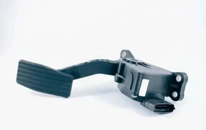
The accelerator pedal sensor or accelerator pedal position sensor shows the position of the accelerator pedal. It converts your foot pressure into electronic signals and sends it to the car computer to increase or decrease the engine speed.
The position of the accelerator pedal is important feedback to the ECU, as it affects the amount of fuel and air that is delivered to the engine. The sensor helps to ensure that the correct amount of fuel is injected and that the engine operates at optimum efficiency.
If it fails, it can cause problems with engine start-up and performance. In some cases, the engine may not start at all. In other cases, it may run rough or stall unexpectedly.
Following is the basic article that will provide readers with an overview of what the accelerator pedal position sensor is, the six-pin wiring diagram, and its types.
Related Post: What Are The Symptoms Of A Bad Accelerator Pedal Sensor
A Little Background
From a technical standpoint, there are two ways you can find the position of something, the first one is contact type, and the second one is non-contact type. The contact type position-finding tool is the potentiometer. And the non-contact type position-finding tools are the Hall Effect and Inductive type.
Contact Type Position Finding Tool (Potentiometer)
The potentiometer is a contact type position finding tool, used to find out the mechanical position of something. The potentiometer is a resistor by which you can measure the voltage difference of a circuit.
Non-Contact Type Position Finding Tool
Non-contact type position-finding tools are Hall Effect and Inductive type sensors. If you want to know the position of something without having a physical connection, then you can use Hall Effect or Inductive type sensors. These sensors are used for detecting the position of a moving shaft, and speed detection.
These sensors are most commonly found in wheel speed sensors (ABS Sensor), and cam or crankshaft position sensors for calculating the revolution of the rotating (RPM) shaft. This was a little about the background to understand the topic in a better way. Now come to the topic.
Related Post: How To Test Coolant Temp Sensor Wiring With Multimeter
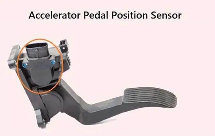
What Is Accelerator Pedal Position Sensor
The accelerator pedal position sensor or AAP sensor is a part of the drive-by-wire system, which measures the location of the accelerator pedal. It tells the electronic control unit how far the accelerator pedal is depressed. It is mounted on the accelerator pedal or sometimes on the throttle body.
It converts the accelerator pedal movement into an electronic signal, which then increases or decreases the engine speed by controlling the fuel flow to the engine.
The electronic control unit receives the electronic signals from the accelerator pedal sensor, combined with other feedbacks like RPM, air temperature, speed of the vehicle, etc, and decides how much fuel to be left in the engine.
Inside it, there are two or sometimes three position sensors fitted with individual wirings. This is because, safe throttle operation and redundancy mean if one sensor fails, the other two sensors give the signals to the engine control unit and behave as a backup sensor so that your auto does not stop at the highway and the driver can reach the workshop.
This turns the car into a limp mood and reduces the speed by no more than 35 miles per hour. The first sensor is the primary input to the computer and the other sensor’s readings are opposite to the main sensor means if one sensor’s voltage increases; the other sensor’s voltage decreases.
When the accelerator pedal is depressed, the computer continuously compares the output of all two or three sensors. If either one sensor fails, the performance will decrease. It uses a potentiometer, hall effect, or inductive-type sensor to measure the location of the accelerator pedal.
The accelerator pedal typically has a voltage range of 0-5 volts. This means that when the pedal is pressed, the corresponding increase in voltage will be between 0 and 5 volts. The reason for this range is that different vehicles have different sensitivities to pedal feedback. Some vehicles are designed to be more responsive to small changes in pedal position, while others are designed to be less sensitive.
This is an Info
Some accelerator pedal sensors are removable, and some are integrated into the accelerator pedal.
Related Post: What Is Throttle Position Sensor & Its Types
Types Of Accelerator Pedal Position Sensor
It measures the position of the accelerator pedal in two different ways.
- Contact type
- Non-Contact type
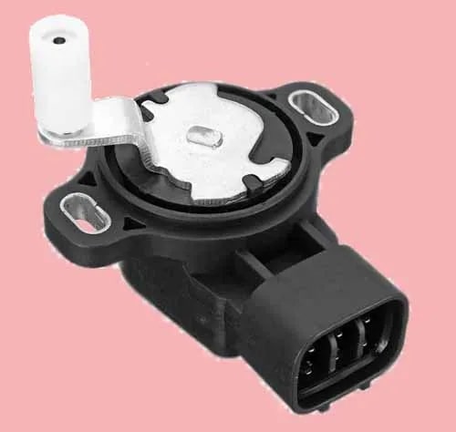
1. Contact Type Accelerator Pedal Position Sensor (APPS)
Contact type APPS sensor is of potentiometer type. Below is the explanation of the potentiometer-type accelerator sensor (APPS).
Potentiometer Type Accelerator Pedal Position Sensor (APPS)
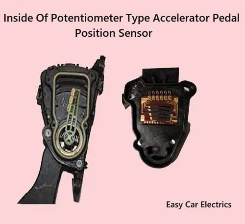
In contact types APPS sensors there is a potentiometer ( a type of resistor, which measures the voltage difference) where a wiper blade slides on a strip that changes the voltage and sends it back to the computer.
Whenever the pedal position is changed, the potential difference of the potentiometer also changes, which is sent to the automotive computer. Due to having physical connections in the potentiometer such as the wiper and connector, it is more prone to wear and tear.
Related Post: Starter Motor Diagram
6 Pin Accelerator Pedal Position Sensor Wiring Diagram
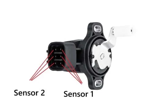
Some accelerator sensors (APPS) have two or three potentiometers inside the APPS sensor with individual wiring. A potentiometer consists of three wires, earth, voltage, and a signal wire (wiper), which moves against the resistor to send back the voltage signal to the computer. A dual-contact type potentiometer APPS has six wires.
So, a 6-pin accelerator pedal sensor wiring diagram consists of two ground wires, two wiring lines for the input voltage, and two signal lines returning to an engine control unit.
2. Non-Contact Type Accelerator Pedal Position Sensor (APPS)
The non-contact-type accelerator pedal sensor is of hall effect and inductive type. In the Hall Effect and Inductive type sensor, a voltage is produced when the object comes closer to the sensor, this voltage is sent to the computer (ECU) to calculate how far the throttle butterfly valve should open.
It also has two or three-wire Hall Effect or Inductive type sensors with individual wirings. Below is the explanation of the hall effect and inductive type of sensors.
Related Post: Starter Solenoid Wiring Diagram
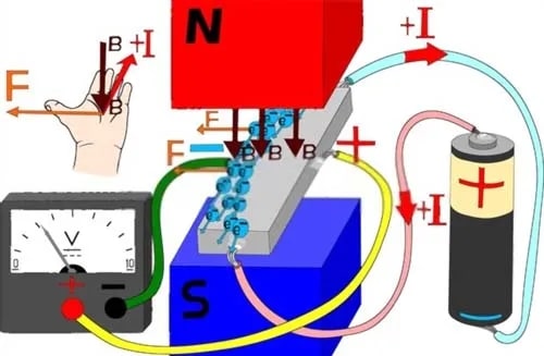
Hall Effect Type Accelerator Pedal Position Sensor (APPS)
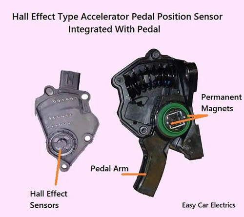
These types of sensors have a magnet and a steel-type material like germanium, so when an object comes closer to the sensor, its magnetic flux changes, and as a result, voltage is produced.
It consists of three wires; voltage, ground, and signal wires. The voltage needed for integrated electronics (transistors), is usually 5 volts, but in some cases, can be 12 volts.
And the other two wires are the ground and signal wire (the wire goes to the computer from the sensor). This voltage is very low; an amplifier circuit is built up in the sensor to amplify the voltage.
This is an Alert
In the Hall Effect and inductive type sensor, there is no physical connection with the accelerator pedal, hence no wear and tear, and has a long life.
This is an Alert
Sometimes, the Hall Effect accelerator pedal brushes get worn out due to usage. As a result, the pedal does not rotate smoothly, and rough acceleration happens.
The Inductive Type Accelerator Pedal Position Sensor (APPS)
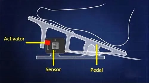
The inductive type non-contact accelerator pedal sensor consists of a sensor (magnet and coil), and an activator (steel). When the activator comes closer to the sensor, voltage is produced, which is sent to the computer. It has two wires, an earth, and a signal (voltage) wire.
This is an Alert
As the voltage produced by these sensors is very low, it can be easily distracted by wave signals, so a coaxial shield coat is applied to the wire to protect it from wave signal distraction.
Difference Between Hall Effect And Inductive Type Sensor
The difference between both sensors is, that the Hall Effect must be given the voltage, without providing the voltage, it would not work, because the Hall Effect sensors have an integrated circuit and need an external power source to operate, which amplifies the voltage.
That’s why it has three wires, earth, voltage, and a signal wire. The coil or inductive type sensor needs no external voltage because it produces the voltage itself when an object comes closer to it. And it has two wires earth and a signal wire. It does not need a voltage source to function.
Frequently Asked Questions (FAQs)
The accelerator pedal in a car typically has a voltage range of 0-5 volts. This means that when the pedal is pressed, the voltage sent to the engine will be between 0 and 5 volts. The specific voltage will depend on how far the pedal is pressed.
There are several key differences between the throttle sensor and the accelerator pedal sensor. First, the throttle sensor measures the angle of the throttle valve, while the accelerator pedal sensor measures the pedal depression angle. Second, the throttle sensor is used to detect engine load, while the accelerator pedal sensor is used to detect the driver’s intention. Third, the throttle sensor is installed on the throttle body, while the accelerator pedal sensor is installed on the accelerator pedal.
Throttle control repair and servicing typically involves inspecting the control for damage, repairing any damaged wires or harness, cutting off any frayed ends, connecting it to a new terminal, and performing a full service to ensure the control is functioning properly.
Sign Up