Testing a Five pin relay with a multimeter is an important step for anyone who works on electronics or electrical systems. It is essential to ensure that these relays are functioning properly and up to the desired standard. Knowing how to test a Five pin relay can be intimidating for those without any prior experience, but this article will simplify the process and provide clear instructions.
A relay is a switch that helps power to flow in certain directions. The Five pin relay is a type of electrical device used to flow the current and voltage in an electrical path. It is an important piece of equipment that can help regulate the power supply in a variety of applications. Testing a Five pin relay is not difficult, but it does require the right tools, including a Multimeter. In this article, we will explain how to properly use your device to test a Five pin relay and ensure it is functioning as expected.
How Car Relay Works
Before we start testing the five-pin device. It is important to know how a car relay switch works. Consider it as two halves. One is known as the loop path (also called a low voltage path, a low amperage path, controlling path. The second half is called a load path or high amperage path.
Keep in mind that the load path is controlled by the curling circuit. When a current is applied to its’s coil current path, a magnetic field is created due to the electromagnetic effect that attracts the movable rod and establishes a physical connection between the high-amperage current path.
On the other hand, if the electric current is removed from the loop current path, the movable bar will return to its original resting location, enabling it to disconnect the high-amperage current path.
Related Post: Car Relay Guide: What it is & How A 12V Relay Works
What Is A Common Terminal, Normally Open Terminal, And Normally Closed Terminal in 12V Relay
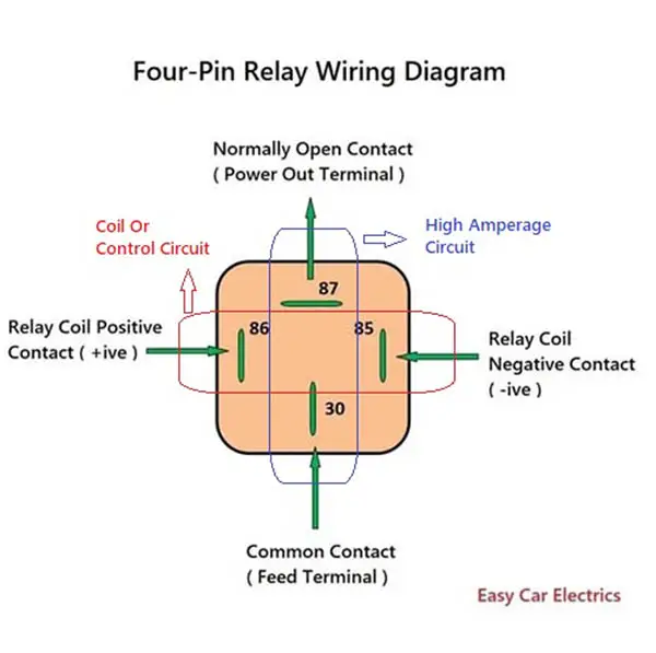
A common end is a that is used to connect the power source to it. The com terminal is usually labeled as end 30 in its wiring diagram. The normally open (NO) is one that is open (not connected) by default. It is usually labeled as terminal 87 in its wiring diagram.
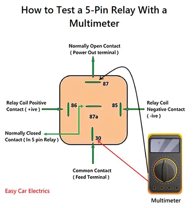
The normally closed (NC) is one that is closed (connected) by default. It is usually labeled as end 87a in the wiring diagram. When it is energized, the normally open will close and the normally closed will open.
Tool Required To Test a Relay With Multimeter
To test a 5-pin relay using a digital multimeter, you will need the following tools:
- Digital Multimeter (DMM): This is the primary tool used to test it and measure linking, voltage, the resistance between the two terminals, and current.
- Protective Equipment: This includes safety glasses and gloves to protect yourself from electrical hazards.
- Battery: This is used to power it during testing.
- Jumper Cables: These are used to connect them to the measuring instrument and the battery.
Safety Precautions
- Make sure to put on safety glasses and gloves before working with electrical equipment to stay safe.
- Read and follow the user manual of the DMM and any other tools you use to understand how to use them correctly and safely.
- Always disconnect the battery and check that there is no power running through the circuit before testing it.
- Be cautious when handling electrical components, as they can be hot and cause burns or electrical shocks.
- If you lack experience or qualification, avoid testing it or working on electrical systems.
It’s important to follow proper safety precautions when working with electrical systems and to consult the user manual of this device and other tools to understand how to use them safely.
How to Test a 5 Pin Relay With a Multimeter
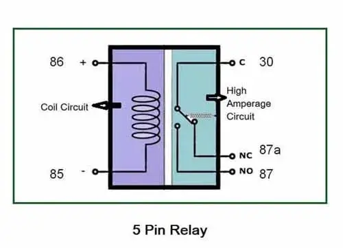
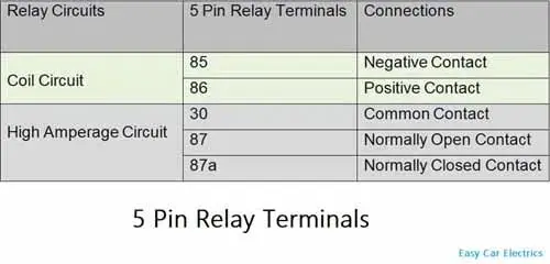
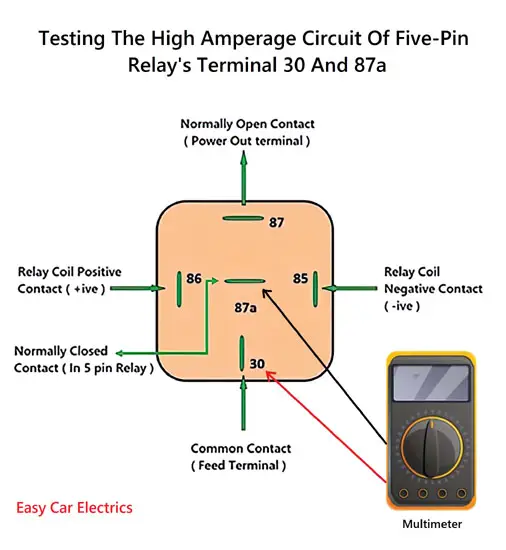
A relay has two current paths, a coil current path, and high amperage current path. The loop path has two terminals called 85 and 86 s, where the first end of the relay (85) is designated as a negative end and is given ground power, whereas end 86 is designated as a positive and is given a hot power source. The loop circuit is the that when you pass the power, you hear a clicking noise.
High amperage current paths have three terminals called 30, 87, and 87a, in which 30 is a common terminal and 87 is a power-out terminal, indicating that the 12-volt supply exits from it to the component. There is also a third 87a which plugs into the five-pin device. This terminal is required when power is not required while simultaneously energizing it, and by energizing it, power is cut.
Related Posts:
- Automotive Relay Diagram: 4 & 5 Pin Relay Wiring Diagram
- Types Of 12V Automotive Relays – 3, 4, & 5 Pin Relays
As the name implies, the five-pin relay has five pins. Two pins control the loop, and the other three pins switch power from one current path to the other. It can be tested using a Multitester to measure voltage, resistance, and electric current.
We will divide the five-pin relay into two categories (Electromagnetic Coil current path and High Amperage current path) and will test both categories. Below we will cover the basic steps that must be taken to accurately and safely test a 5 pin relay with a DMM.
- Testing Relay’s Coil Circuit
- Testing Relay’s High Amperage Circuit
1. Testing Relay’s Coil Circuit With a Multimeter
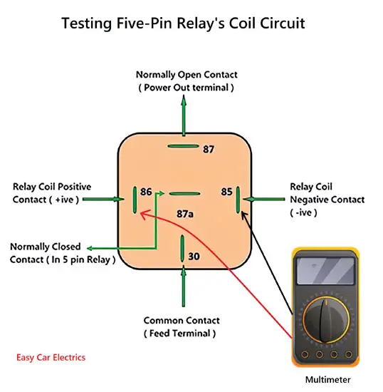
Its loop current path contains pins 85 and 86, which are the two pins on the sides. The first step involves testing the resistance flowing through the coil’s current path. You will have to switch the multimeter to resistance measurement mode.
- Connect the two leads to the Multitester. Note that the polarity does not have any effect on the resistance. It allows you to connect the input jack to any pin.
- Once the leads have been connected, observe the DMM reading on the screen to check whether the relay is working well or if you are having a malfunctioning relay. The resistance of the current path’s loop is approximately 50 to 120 ohms if the relay is in good condition. If the reading is within the specifics of the mentioned figures, it means the relay coil is in good condition. However, the coil is faulty if the reading is not within the specifics of the mentioned figures, which could be either high or low. At this point, you will have to replace the coil if the coil is not repairable.
2. Testing Relay’s High Amperage Circuit With a Multimeter
The next step is to learn how to test the relay’s high amperage path. The high amperage path contains three pins 30, 87, and 87a. We will test pins 87 and 87a with respect to pin 30. For this, you will have to switch the DMM to resistance mode. linking mode testing also involves checking the end to confirm if it is open or closed. One of the best ways to check a relay is to test the resistance between the ends. Below is how to carry out the tests.
- Testing Pins 30 and 87
- Testing Pins 30 and 87a
Caution: Do not use an ohmmeter to measure ohms while communicating with a live wire. The volts can harm the ohmmeter while studying the resistor while a current is flowing. Here, I’m referring to the amperage path of it. Do not use an ohmmeter when the high amperage path is connected to the source of the power.
A. Testing Pins 30 and 87 Of the Five-Pin Relay
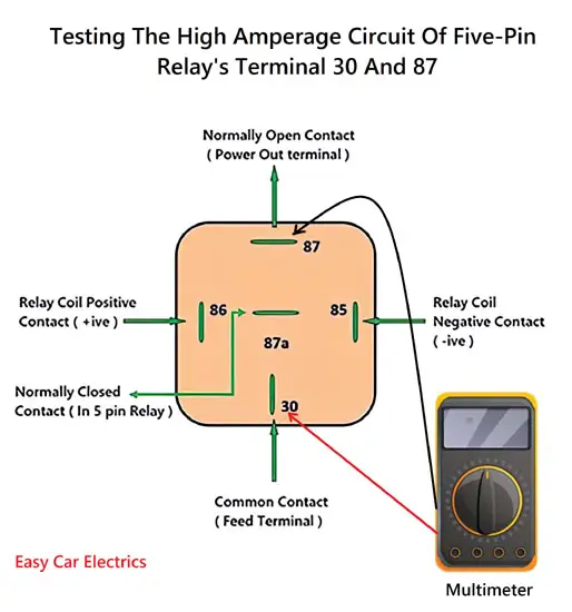
- To test pins 30 and 87, first, ensure that the DMM is switched to resistance mode. Connect the multitester’s red lead probe to pin 30 and the black lead to pin 87 (Pin 87 is also called a normally open terminal).
- Now, energize it by giving power to the relay’s coil path. When it is energized, pins 30 and 87 will start to have linked. During the test on the Five pin relay, if the value of resistance is too low or near zero, then the pins are working properly. If the ohmmeter checks for resistance on the pins 30 and 87 paths by its abbreviation, OL, which means that Open-Loop or Open Load or with very high resistance. It means that the path is open and does not have connectivity, which indicates whether the relay is defective or the terminals are faulty.
- You can also test pins 30 and 87 by using a multitester in linking mode. The linking mode of the multitester also emits a beep when a closed path is detected, indicating that the linking of test leads has been established.
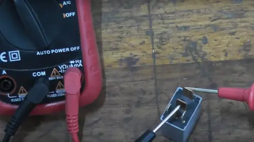
B. Testing Pins 30 and 87a Of 5-Pin Relay
We will test pins 30 and 87a. Pin 87a is also regarded as normally closed. To start determining whether the relay normally closed terminal is faulty or not, ensure the DMM is switched to resistance. Proceed to connect the red lead to pin 30 and the other black lead end to be connected to pin 87a.
- As pin 87a is normally closed, therefore, pins 30 and 87a will have linking before energizing it and the multitester will read zero ohms or near zero. The resistance between the com and normally closed terminals should be zero ohms. However, if by energizing relay contacts, the path between pin 30 and 87a is still intact, the relay in your connections is faulty and you need to replace the relay. It should be disconnected by energizing it.
- Now, energize it, and the continuity between connection pins 30 and 87a will break and the path linking will shift between pins 30 and 87. If the multitester reads zero or close to zero ohms by testing pins 30 and 87, then it is working fine. However, if the ohmmeter reading shows an OL current path. This means that the current path is open and there is no connection, indicating a faulty relay component, linking mode in the DMM also emits a beep when it detects a closed current path, indicating that there is a link between the test leads.
Conclusion
Testing a Five pin relay with the probe of the multimeter is a simple process that is not too much time-consuming or difficult. You must first identify the pins and their corresponding functions in order to properly assess it. After you have done this, you can begin testing your 12v relay by setting your DMM to ohms and measuring the resistance between each of the pins. If you do find any issues with it, replacing it may be necessary depending on its function and importance in the current path. Bear in mind that you must not fix a damaged relay.
Related Posts:
- How to Test a Car Relay With & Without a Multimeter
- How to Test a Relay With a Battery (With Pics): The Easy Way
FAQs
To test a Five pin relay present in cars without an image, you can use a DMM and put the probe of the multimeter to the com terminal and each of the other ends to test the pins that control the coil and the normally closed pins.
A relay is a type of switch that is activated by a small current, typically much lower than the current required to operate a typical mechanical switch. The main difference between a relay and a regular switch is that it uses an electromagnet to close or open its contacts, whereas a switch relies on mechanical movement to complete or break a current path. Additionally, it can be configured to function as a normally open (NO) or normally closed (NC) switch, depending on the type of relay.
To test the terminals of it with a multitester, you will need to set the DMM to measure either low current or high or very low resistance. First, make sure it is disconnected from any power source. Then, connect the multitester to the COM and NO terminals of the relay, and apply a small current to the input of the relay. If it is working properly, the DMM should show low resistance or low current when activated, indicating that the switch is closing. If it is not functioning properly, the DMM will show high resistance or no current flow, indicating that the switch is not closing.
To test the contacts of a Five pin Relay with the use of a digital multitester, you can put the multimeter probe on the common terminal and the other probe on each of the other terminals to check the resistance and ensure that it is functioning properly.
A guide on how to test a relay without an image is a set of instructions that explains how to use a DMM to put the probes on the com terminal of relay and each of the other terminals to test the pins that control the loop current path and the normally closed pins, as well as how to use a 12V source to see if the switch will open and close properly. It also explains how to check the resistance of the contacts of the relay to ensure that it’s functioning properly and how to replace it if necessary.
Sign Up