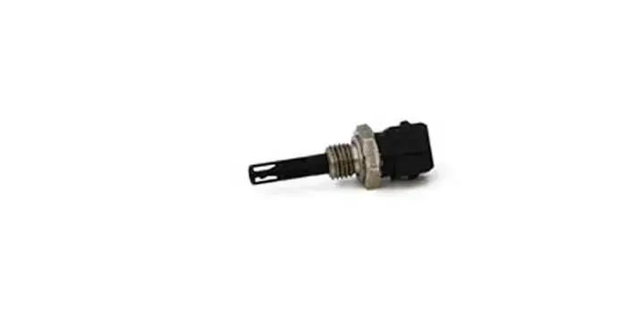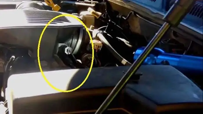
The IAT or intake air temperature sensor measures the temperature of the air and sends it to the ECU of the engine. The ECU then uses this data to calculate the correct stoichiometric amount of fuel to be injected into the combustion chamber of the cylinder.
The wiring diagram of the IAT can be different based on year, make, and model. The IAT sensor wiring diagram is the same for every car, but its color varies according to the brand.
In this guide, I will give you a general idea of the wiring diagram of the IAT sensor. For your specific make and model, you should visit your car owner’s manual. The wires are color-coded according to the make and model. You can consult the proper wire diagram for your car for accurate wire color.
Related Post: Intake Air Temperature (IAT) Sensor, How It Works & Function
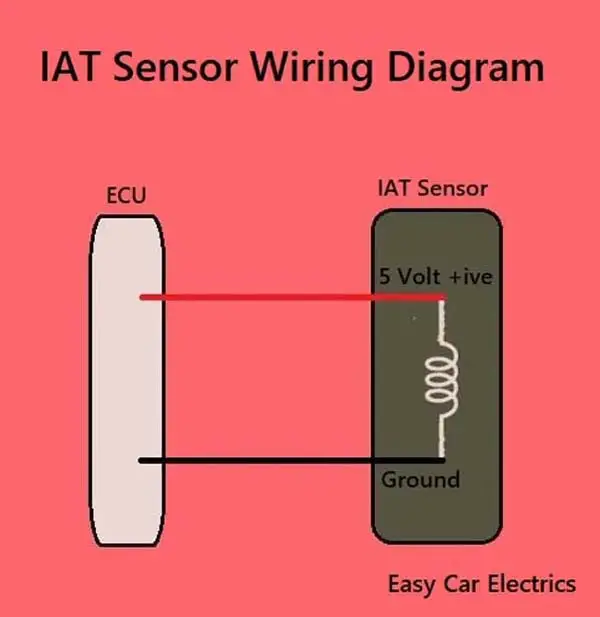
IAT Sensor Wiring Diagram

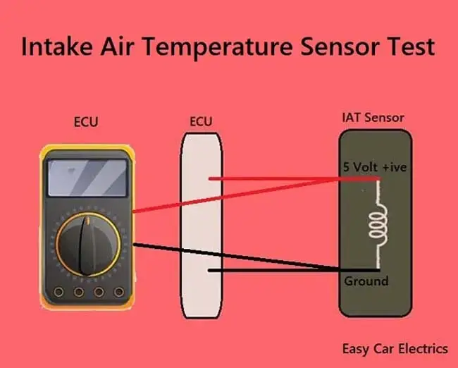
An intake air temperature sensor or IAT sensor has the following two wires.
- 5-Volt Reference Wire
- Ground Wire
The IAT sensor has two wires, which come from the ECU. A positive current is supplied from the ECU to the IAT sensor and goes back through the ground wire. A 5-volt is sent to the intake air temperature sensor through a 5-volt reference wire.
In the IAT sensor, the resistor opposes the current according to the temperature, the higher the temperature, the lower the resistance, and vice versa. And the remaining current from the IAT sensor goes back to the ECU through the ground wire.
The ECU then analyzes the voltage received back to it and gets to know the temperature of the air through pre-programmed values. The IAT sensor outputs a voltage close to 4.7 volts with very cold air and 0.8 volts with very hot air. According to the temperature, the ECU then decides how much fuel to allow into the cylinder for combustion.
Here you should remember that the signal wire means a wire, which sends back the signal (Voltage) from the Sensor to the ECU. And a reference wire means a wire, which sends the voltage from the ECU to the Sensor.
So, here the ground wire also works as a signal wire because it sends back the output voltage to the car ECU. In the latest model car, the IAT sensor is built into the MAP and MAF sensors.
Here you can know the wiring diagram of the MAP and MAF sensor.
Related Posts: 3 & 4 Pin MAP Sensor Wiring Diagram
: 5 Wire Mass Air Flow (MAF) Sensor Wiring Diagram
Frequently Asked Questions (FAQs)
IAT, or Intake Air Temperature, sensors are not typically responsible for making a car not start. There are a number of potential reasons why a car might not start, including issues with the battery, spark plugs, or fuel system. It’s possible that an issue with the IAT sensor could contribute to a problem with the car not starting, but it’s unlikely to be the sole cause of the issue.
The IAT sensor measures the temperature of the air going into the engine. The engine control unit uses this information to adjust the fuel/air mixture. If the IAT sensor is not working, the engine will run but it will not be able to adjust the fuel/air mixture properly. This can lead to poor engine performance and increased emissions.
Sign Up